|
|
Post by Mofo on Oct 22, 2013 18:01:05 GMT -7
Ah, the joys of scratchbuilding. I’ve been working on the landing gear. Spent a ton of time digging up references. The kit parts are way out, so I couldn’t use them for anything more than crude dimensions. None of my scale drawings include more than a rough outline. Found a ton of great detail photos, but nothing that would let me nail the overall geometry, so I spent an afternoon with a calculator and graph paper trying to work out a plan. Started sketching it in CAD, wasn’t really happy, stopped. On the weekend, I found a fantastic shot of a main gear strut removed from the fuselage, all on its lonesome. Perfect – it’ll let me sort out (most of) the shapes. Spent a full day working that up in Solidworks. Got a rough model going, ran into some problems, sank a bunch of time into fixing them and trying to figure out some questions. *Last night*, while cruising around the ‘net, I stumbled across some detailed, accurate scale drawings. *Perfect* reference, rendering all my previous work completely obsolete. Sigh. 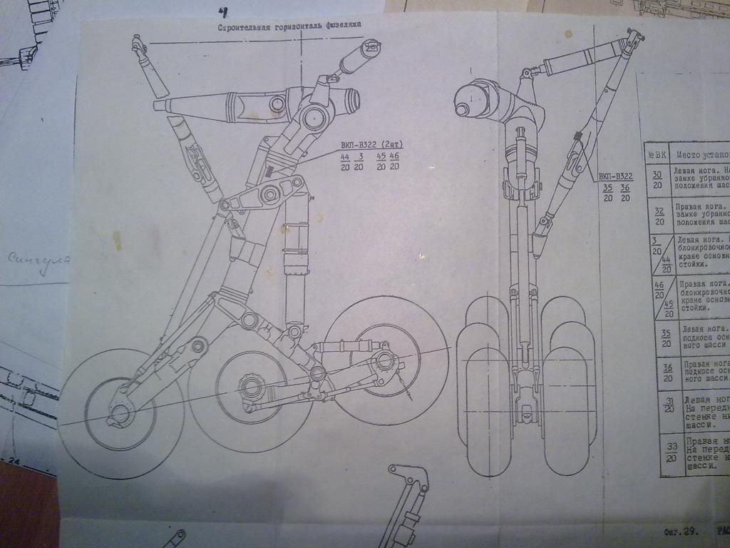 So here we go with Mk.3... Sketched over the scale drawing in Illustrator. Cleaned up in Solidworks (nearly done), then I'll start working on turning it into a 3D object. I just wonder what information I’ll turn up once I’m heavily into THIS one! 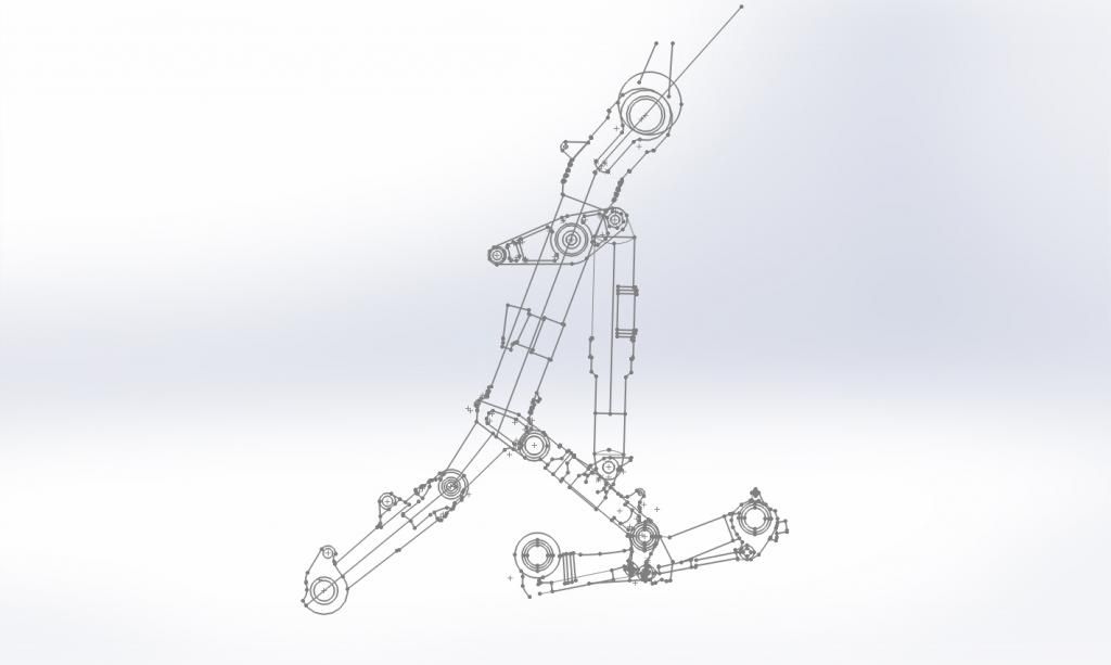 eta: on the plus side, I also found some fantastic references for the flaps, which will take all the guesswork out of cranking those out, so I guess I won one there. |
|
|
|
Post by Mofo on Oct 25, 2013 10:00:55 GMT -7
Drawing done, the struts have been rotated for weight on wheels and all oleos rotated/compressed. Now the fun part begins. 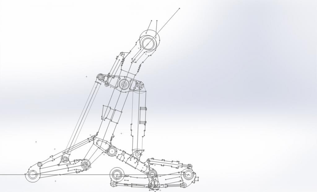 ...and for comparison's sake with the kit parts: 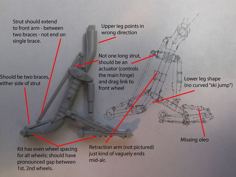 |
|
|
|
Post by Mofo on Oct 29, 2013 22:56:09 GMT -7
Not that anybody cares, but the MLG struts are nearly done. Kinda fun that you can attach the CAD wheels to the CAD MLG to get a feel for the finished assembly: 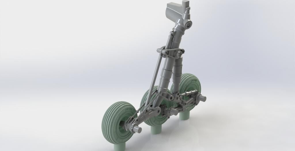 The tops are a little funky in an effort to blend the actual shapes with a workable kit part, but they'll be hidden up in the gear wells anyway. I've installed a locating pin and bulked up the gluing surface for a nice, secure join. ...and quite possibly the greatest thing of all when it comes to doing stuff on the computer. Click the magi "mirror" button aaaaand... 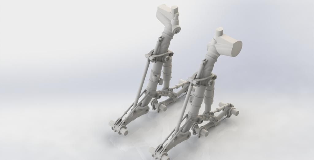 An identical part for the opposite side. No need to do everything twice. No worrying if everything will match up. Next up: the MLG retraction arm, followed by the nose landing gear. Might take a break and do the flaps in the mean time, though. BTW, here's the kit retraction arm:  Seriously, take a good hard look at that. The entire MLG in the kit is just laughable when really look at it. It would be completely non-functional, as tooled. The MLG strut has actuators and hinges, but none of them could actually function, since they're either attached to non-hinged structures or else they're fused solid by bolts and struts when they'd need additional oleos. And I can't imagine what that retraction arm is supposed to do. The *only* explanation I can think of is that the Trumpeter designer/s found the same scale drawings I did, and somehow translated the head-on view on the right side as having the two protrusions attached. Because they do, kinda, sorta, look that way. *EXCEPT*, how on earth could you be employed in any sort of capacity working with blueprints and drawings and not have even the slightest clue how to actually read a drawing (if you are paid to design stuff from drawings, and you can't tell the rough geometry depicted there, you should no longer be paid to design stuff from drawings). And #2, if they had that drawing to work from, how could they get everything else about the landing gear so completely wrong?!? Sorry, but it's almost like they're being willfully negligent at this point. (don't even get me started on the K-36 seats they decided to include for the cockpits...) |
|
|
|
Post by paolo6691 on Oct 31, 2013 11:57:22 GMT -7
They look great!
Thats a lot of work, for the gear and the flaps
|
|
|
|
Post by Mofo on Nov 13, 2013 14:27:34 GMT -7
The gear... yeah, that's a ton of work. Guessing, tweaking, re-working, making sure the dimensions will print and the detail will stand out. And then just sketching it all out.
Flaps? Yes and no. The flaps themselves are fairly straightforward. The tricky part is trying to piece together the geometry from a bunch of detail pics (there aren't any great, clear shots of the general area that I've found, which would put the whole area in context, so I'm trying to build a mental picture from a slew of close-ups). Plus, the kit has all the right panel lines, but I'm not convinced that they're in the right locations, so I've got to figure out how the real thing relates to the kit, where the panel lines *should* be, and how to make it fairly easy for the modeller to put it all together.
Basically, making flaps? Easy. Making flaps that fit the kit? Frustrating.
|
|
|
|
Post by Cap'n Wannabe on Nov 13, 2013 18:22:27 GMT -7
Great work there, Mofo!
|
|