|
|
Post by Mofo on Apr 5, 2014 15:38:27 GMT -7
Day 1: Zepp Scratchbuild.  Actually, I guess technically it began a while back - I first started investigating plastic suppliers in November, finished off the drawings... January? Printed out the templates a month an a half ago. Ordered the sheet styrene like a month ago now (no problem, it'll be in tomorrow!)... I *finally* got the sheet stock today. A 4 x 8' slab of .020" styrene. Damn, that's a lot of plastic. And *cheap* - it was under $15. (this was about $0.50/sqft. Evergreen works out to about $2.50/sqft!). Plus a 6' rod of 1/4" square acrylic, and three lengths of 1/8" acrylic rod for the spine. I also got my hole punch last week (works surprisingly well), so I'll be spending the next few weeks cutting bulkheads. The plan is this: I'm building a 1/144 Q-Type Zeppelin. I *briefly* toyed with the idea of doing it in 1/72, but it was too big to be feasible, so I'm settling for the smaller scale. It should be about 4' long when finished. The build is based heavily on this paper model. jleslie48.com/zep/model_parts/Pclass_description.pdf jleslie48.com/zep/model_parts/ I took his dimensions and layout and plotted each bulkhead in CAD, translated those dimensions to curves to make the skin, then printed the templates out on 4x3' sheets. I also added some locating marks to each bulkhead - I'll be running the 1/4" square rod down the middle (square cross section keeps everything aligned), with the 1/8" rods spaced out in a triangle to add rigidity and keep the individual bulkheads from flexing. Once that's all glued up, I'll start laying on the skin sections to cover the model. So the first step will be to attach my templates to the styrene sheet. I plan to use spray-mount to stick them on; it should be tacky enough to hold, yet easily removed later on. Then, it's just a matter of cutting precisely up to the lines, and sanding flush. x1500-odd times.  X-Acto chisel blade to trim out the slot for the square spine, then hole punch to knock out the 1/8" rod locating holes. |
|
|
|
Post by Mofo on Apr 7, 2014 15:56:02 GMT -7
Update from day 2. 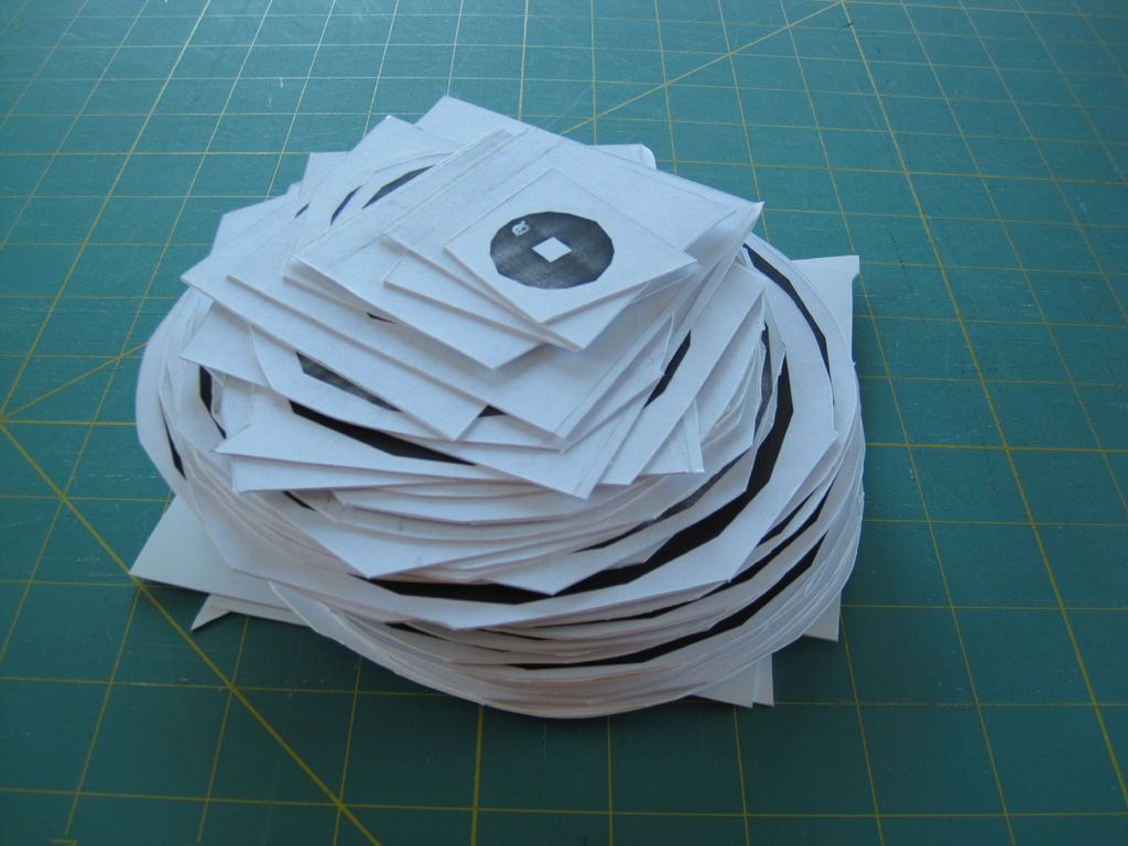 Here's the stack of bulkheads, roughly trimmed from the styrene sheet. I spray-mounted the printed 4 x 3' templates onto my 4 x 8' styrene sheet. Nothing really interesting to see there. These were then burnished down to remove any air bubbles, then I roughly trimmed each bulkhead from the sheet. 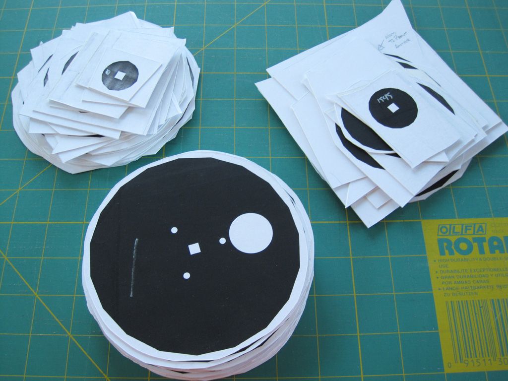 Three stacks. Top left is the aft tapered portion (starting from the first frame - 0m - Zeppelin frames seem to have been numbered, in metres, by distance from the rear-most unit, so the tip or the tail would actually be -50 or so). Top right are the bulkheads for the nose section - 1545m from the first bulkhead. The bottom stack are all the constant cross-section centre section bulkheads. Note the square (soon to be) hole in the middle of the bulkheads for the spine, and the three small holes for the reinforcing braces. The large circle in the centre section bulkheads is just an easy way to identify them.  Scrap. I should probably peel the paper off and figure out how to strip the spray adhesive; this should keep me in scrap styrene sheet for years to come. I've also got about 4 x 3' remaining from the full sheet. I *may* use this to scratch the gondolas. Possibly. 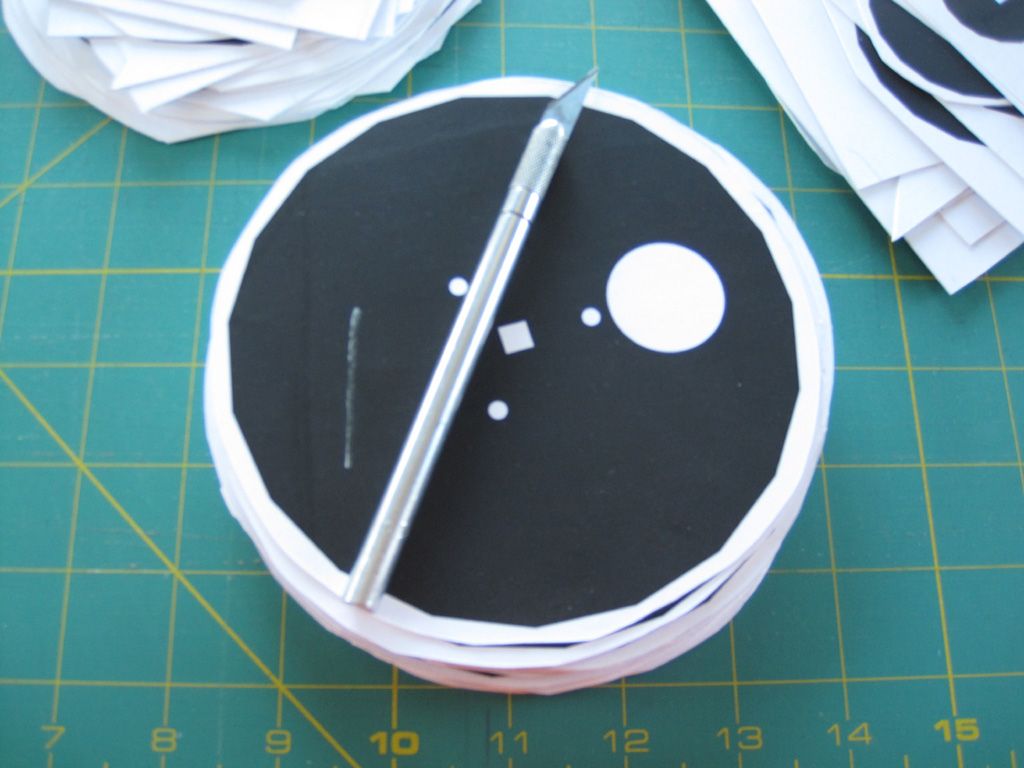 This should give a decent feel for the diameter of the balloon. It'll have .040" of styrene skinned on the outside, obviously, but it's fairly indicative. About 5 1/2" across x 48" long. I'm *seriously* tempted to hack out space for some helium balloons...   ...and the fins. Left are the horizontal surfaces. Middle is the rudder and keel. I'll glue together a pair of each (so, .040" thick), then skin them in .005" to give a slightly hollow, scooped out look. Hopefully... Left are some assembly jigs to set the spacing between the bulkheads. Spacing varies from 40 - 50m on the real thing. Theoretically, I'll be able to slide these between the bulkheads to set the height, rather than meticulously measuring everything. They should also help keep the bulkheads square and plumb as I'm building them up. I hope. So... now that everything's roughed out, I get to start the lengthy process of careful trimming. Next update in a few months.  |
|
|
|
Post by Mofo on Apr 8, 2014 19:34:04 GMT -7
Tonight's update: Good news, bad news. I've trimmed out the bulkheads for the full nose and tail sections. That's about half of the bulkheads needed for the ship. Yay. I've started playing with the... wings? Control surfaces? Whatever... Not so good. The frames are too delicate to trim around, and are deforming... and I haven't even started on the rudders yet. Right now, I'm debating whether to print them out or glue strip stock on top of solid centre sections. Definitely would have been easier if I'd laser cut the parts (as would the bulkheads!) The benefit of 3D printing is that I can give the rudders a nice airfoil cross section, which would be tricky to add to the plastic parts. Bulkheads... I started out trying to score and snap around the edges using a #11 and a straightedge, but the cuts needed a lot of dressing. So I switched to a chisel blade instead - line the chisel up with the template, give it a whack and move along. It's given me much cleaner, sharper edges. Yay. The square cutouts in the middle were handled the same way, and the bulkheads fit nicely on the acrylic rod spine. For the circular holes, I started out using the hole punch, but it just wasn't working well. Because of the thickness of the walls on the tool, it was creating a large, stretched out cone around the hole. Boo. Plan B was to drill more-or-less-the-middle of the holes with a 1/8 bit in a motor tool (precision not super necessary), then refine it with a round file. I realized I didn't have to be super precise, as I can just flow some CA in to lock them in place, so this is "good enough". I've also cut the rods to length. Unfortunately, while I cut the spine to the right length, I messed up the measurement on my bracing rods. I've marked the bulkheads with their station numbers, which correspond to the 154.5m P class... not the 50' longer Q class. D-oh. So when I carefully measured out the scale measurement, it was for the wrong type. I'll probably have to splice in another 4" of rod. Not a big deal - I can use some evergreen tube sleeved over for a nice, snug fit, but it is annoying. Onwards and upwards.  |
|
|
|
Post by Mofo on Apr 9, 2014 12:47:47 GMT -7
Not that anyone cares, apparently, but... Started on the centre section bulkheads. I'm about 1/3 done. Slapped 'em in place and had to take a couple of pics: 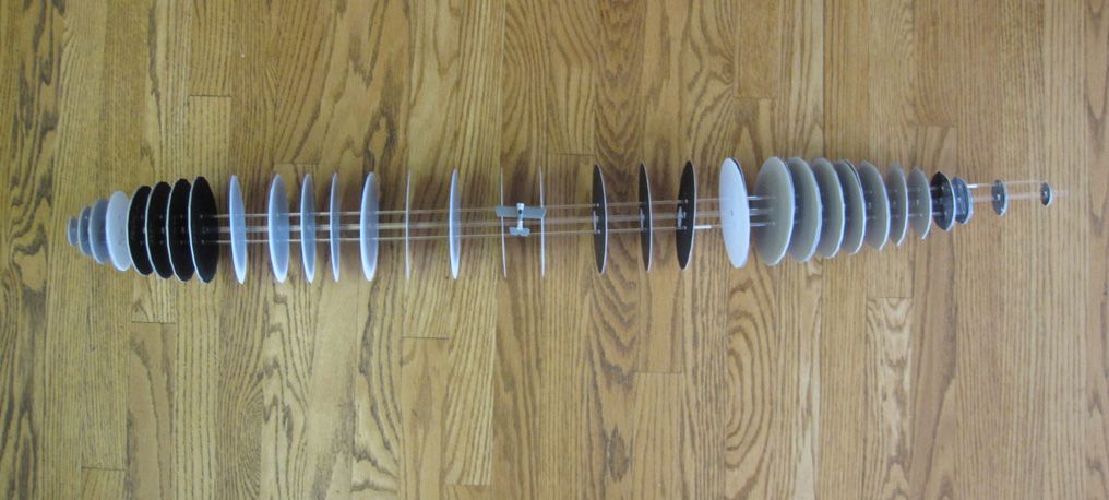 Four feet of fury.  Note the little grey shape in the middle - that's a 1/144 Sopwith Pup... which I'll be building as the specific Pup that killed this specific Zeppelin. Talk about David and Goliath! 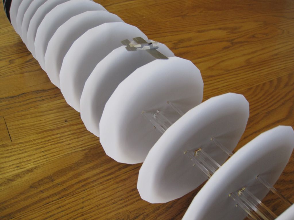 Another shot, to give an idea of the comparative mass of the Pup and Zepp. Pretty sure the Sopwith could have taken off and landed inside the balloon's framework. |
|
|
|
Post by kyrre on Apr 10, 2014 6:02:24 GMT -7
|
|
|
|
Post by gnat on Apr 10, 2014 6:40:09 GMT -7
Now thats going to be an a big undertaking. I built the Graf Zepplin but haven't painted it yet
|
|
|
|
Post by Mofo on Apr 10, 2014 10:07:26 GMT -7
Now thats going to be an a big undertaking. Ain't that the truth. Still kind of wishing I'd splashed out for 1/72 though... but then I start thinking how insanely huge it would have been... I'm kind of worried about paint, though. This one was overall clear doped linen, but as you can see from Kyrre's pic, the upper half in the centre section had a different treatment, so it was "see through". I'm still not sure how I'm going to pull that off... (not to mention, just man-handling the thing while painting! I might have to buy a spray gun to shoot it.  Oh, and Kyrre, is it just Photobucket that's blocked for you? Any suggestions for a different pic host? |
|
|
|
Post by timmay on Apr 11, 2014 6:13:08 GMT -7
Shrink wrap it! P-)Timmay!
|
|
|
|
Post by Mofo on Apr 11, 2014 14:03:43 GMT -7
Shrink wrap it! P-)Timmay! Actually, that's not a terrible idea...  Minor progress: I have decided that I am not happy with the flexible acrylic rod spine. Too much risk of a banana-shaped balloon. So I spent most of yesterday's modelling time looking up alternatives. I can source 1/4" aluminum rod, but that seems too likely to bend, too. 1/4" steel should be rigid, but awfully heavy.  Can't find much in the way of 1/4" tubing otherwise.... Carbon Fiber? The only 1/4" square rod I can find is either sold in much larger quantities than I need (5m lengths) or has crazy shipping ($30 for $5 of CF).  and then. I realize the LHS stocks .196" square carbon rod. Nice and strong, nice and stiff, nice and light. Evergreen do .250" square tubing. Inside diameter is .194". so I can do a *tiny* bit of sanding to make it all fit. Perfect! Current plan is to cut the Evergreen tubing into .040" slices, which I'll CA or epoxy onto the carbon spine at the appropriate bulkhead measurements. I can then use liquid glue to attach the bulkheads to the square tubing spacers. A nice bonus is that the carbon tubing should be a lot easier to mark than the clear acrylic. Otherwise, minor progress cutting out skin sections. I've now got the lower half completely trimmed, just need to do the 6 even sections that cover the top. I'm hoping to force myself to finish them this evening, then it'll just be the remaining centre section bulkheads. 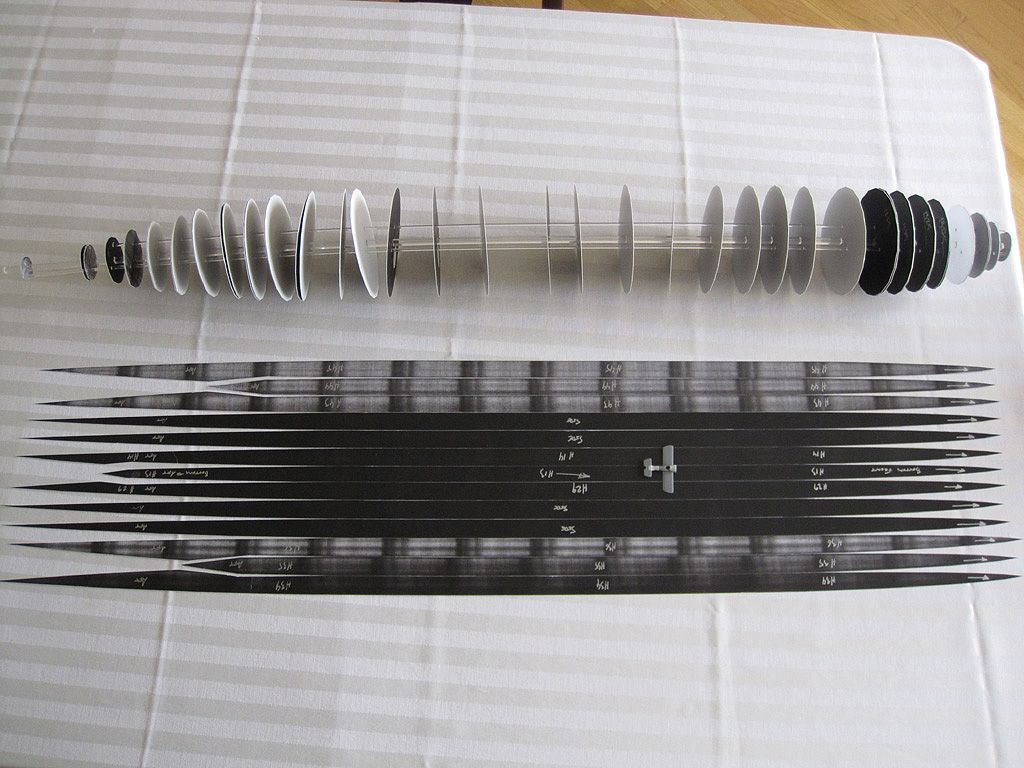 I may(!) start throwing some glue at it this weekend.  |
|
|
|
Post by Dave F on Apr 11, 2014 19:01:56 GMT -7
Watching with interest Mike. Still think you are mad! :-)
|
|
|
|
Post by davefleming on Apr 11, 2014 19:04:01 GMT -7
Oh, I can log in again!
|
|
|
|
Post by Mofo on Apr 11, 2014 22:26:49 GMT -7
Me? Nah, I'm pretty happy.  Actually, a side benefit to this is that it's helped keep my modelling purchases in check. "I'd reeeeally like to buy kit X, but the Zepp is going to take so much of my time, I just can't fit it in the schedule this year." (plus: 1/32 Gotha, 1/350 Koenig and a few 1/12 cars I want to go nuts on; my plate is pretty full for ambitious projects) I've finished cutting out everything except the tailplanes now. Plan to pick up the CF and Evergreen tubing tomorrow; with a little luck, I'll have the skeleton fully completed by the end of the weekend. Then the fun bit starts - skinning.  (and filling/sanding  ) Interesting sidenote: I tried removing some of the spray-adhesive-ed templates from the cut out parts. A touch of Goo Gone per one suggestion I'd read, and it's almost like magic, the paper just falls off. Sort of like spraying Windex on Tamiya paint and watching it all just wash down the drain. Good to know, as the skin panels will all have to be stripped and cleaned. |
|
|
|
Post by Mofo on Apr 12, 2014 23:28:05 GMT -7
Bugger. Did a hobby shop tour today to sort out the spine. One had the CF tubing, and some 1/4" plastruct, but the plastruct has a different wall thickness and wasn't terribly square. Pick up the CF, on to another shop to get some Evergreen then. Got home. Took a good look at the CF tube and.... it's warped. Noticeably. Damnit. So plan C: I'll look into some Aluminium square tube (which only comes in 12" sections, so I'll be ferrule-ing it together with more tubing). My big concern is that it a.) won't be straight and b.) might bend too easily... but it's looking like the only option at the moment. Plan D is to go for either an aluminium round tube or steel wire, which I can slide my evergreen square sections onto, but that means careful gluing or else major alignment issues. Plan E is breaking down and getting some (heavy) 1/4" aluminium or steel bar from an industrial source. Again though, I'm worried about the aluminium's flexibility, and the steel's weight. Grrrrr... On the plus side(?), they were playing around with one of these little suckers at the LHS. Very cool, very tempting.  |
|
|
|
Post by kyrre on Apr 13, 2014 23:59:29 GMT -7
Hey, that Quadcopter looks awesome!
As for your rods I am not surprised they warp. My suggestion would be to use two pieces of aluminium tubing, one inside the other. The outer one will be attached to the bulkheads and be prone to warp, the inner piece will stabilize the assembly.
|
|
|
|
Post by Dave F on Apr 14, 2014 3:19:54 GMT -7
What about Brass tube - heavier than Aluminium, lighter than steel?
|
|
|
|
Post by craig on May 11, 2014 0:29:30 GMT -7
Back in and catching up (not much to catch up on over all). Nice work and definitely watching with interest now that I can see it.
|
|
|
|
Post by Mofo on Jun 9, 2014 21:44:15 GMT -7
Progress! Actually, there's been a bunch, just haven't posted much. Then I stalled. Now I've made more Progress! Gluing on the al. tubing was fairly uneventful. I cut thin slices of evergreen as spacers, glued inside my cutouts (the result of my mis-measuring), then slid them on the aluminium tubing, up to pre-marked lines. I modified a set-square to help alignment: couple lengths of square stock attached with double-stick tape, square, true and plumb, which sat on the square tubing to keep each bulkhead square; then templates were tacked on as a depth gauge to set the distance between bulkheads. Press the square on the rod, slide the bulkhead up to the depth gauge, then squirt on CA. Surprisingly simple and straightforward. Each length of tubing was built up individually, as they were easier to handle. Strangely, the white styrene bulkheads glued to the aluminium tubing reminded me of some Scandinavian-design Christmas tree. As I was press-fitting each completed length together, the assembly slipped, knocking a few bulkheads out of whack, and bending the tubing. Fart. I did a bit of poking and prodding, but pretty much stalled there. 'Bout a week ago, I took a couple of pairs of pliers to the spine, and straightened it all out. A tweak here, a tweak there, and it's pretty much good. Now I've just got to CA the cross braces (which should help straighten it further - and keep it straight), but that's another straightforward job. Just CA and a depth gauge. The major hurdle that has been stalling me is actually the skin. I've cut out all the pieces, but I need to mark off the bulkhead locations. And because they're rounded in cross-section, that's not a simple issue of measuring. I didn't feel like doing the math, so the whole project kind of slipped by the side. *Finally*, tonight I got off my duff and worked all the distances out, drafted a template and printed it up. This probably single-handedly justified my drafting the original templates in Solidwoks (vs. Illustrator), since SW has a handy feature to measure the lengths of curved lines. Once I re-scaled the drawing, the line properties displayed the length. Yay. So tomorrow's task is to glue up those braces, and mark off the skin. And shoot some pics to update the thread. Then I can start the (hopefully simple) task of skinning the whole thing, which *should* make it fully rigid. Then, the puttying can commence.  |
|
|
|
Post by Mofo on Jun 15, 2014 12:14:36 GMT -7
Big news! It's covered.* I made covering the skeleton my Le Mans build. Finally made myself glue up the supports, then skinning was pretty straightforward. Time consuming and glue-smeary, but straightforward. Worst part was having to chamfer the edges of each skin segment. *Lots* of sanding dust and plastic shavings/scrapings. I ended up with a lot of seams, partly from over-scraping and partly from minor assembly issues with the skeleton. Basically, because I cut them all by hand, rather than doing the laser cut thing, I had a couple of degrees rotation on the odd bulkhead, which pushed the skin *slightly* out of alignment, and will have to be dealt with. Shouldn't be too miserable: run a bead of thick CA down all the seams to lock them in place, then probably a coat of Bondo; sand flat over the next month or two.  It'll be tedious and dirty, but it's getting there, and I'm kinda jazzed. Pics to follow. *Except for the added bulkheads. That should be pretty straightforward, though. The BIG job is done. |
|
|
|
Post by Mofo on Jun 16, 2014 19:33:10 GMT -7
FUCK!Disaster struck. The skin was all glued on. Lots of gaps along seams, but a line of gap filling CA would easily solve that. Then a coat of bondo, and a bunch of sanding. Nothing fun, but nothing hard. All I had to do was remove the templates first. I had attached them with spray adhesive. The manufacturer's website suggested a citrus-based cleaner like Goo Gone, or mineral spirits to remove dried adhesive. I didn't think I had enough Goo Gone to strip the whole thing (and didn't want to waste a bottle doing so), so out with the mineral spirits, doused liberally on some paper towels to soak on the surface, with a few extra splashes to make sure. Mineral spirits + styrene = brittle. The skin is cracking on me. Quite severely, in some places. It's breaking, cleanly, along the bulkhead glue lines. A slightly-too-firm squeeze, and it just gives way.    Once I realized what was happening, I soaked them for a good 1/2 hour in a basin full of soapy water, to try to remove all vestiges of mineral spirits and at least halt the damage. I guess I'll do a thorough inspection tomorrow, to figure out where I'm at. With a bit of luck, I'll be able to bulk up the cracked seams with thin CA and make it rigid enough to fill and sand as planned. My concern though, is that it won't hold up to the filling and sanding process - I do *not* want to start punching through the skin later on. I'm also a little worried about how it'll hold up long-term; I don't want it to start crumbling on me a few years down the road, either. Fuck. 
|
|
|
|
Post by timmay on Jun 17, 2014 6:14:43 GMT -7
I feel your pain, Mike. I too had a bad experience years ago on some armor when I applied a wash made with MS. It made most of the glue joints loosen and even made some of the parts come apart at the chill lines on injection molded parts. Another reason I quit using petroleum based products on my models. Except for MEK and Putty. Timmay!
|
|
|
|
Post by Mofo on Jun 17, 2014 22:17:39 GMT -7
Sigh. Well, after a day - and after some poking and prodding to assess the damage - it's not looking any brighter. Not *every* section of skin is pooched, but an awful lot of them are, and it really doesn't take much pressure to start cracking the surface. As I see it, I've got three options. #1 is to CA the seams between the skin panels and flood any cracks with glue or thin CA. Hopefully the CA will give it enough rigidity to hold up to filling/sanding... but I'd kind of like something more certain than "hopefully", and I'd be worried that it would just crumble over time.  Maybe cut out the most effected areas and re-skin, since it's not cracking *everywhere*, but again, will it hold? #2 would be to laminate a second skin. It'd be a lot of work (re-cutting the skin), and laminating would be a big job with an immense contact area (it's a large structure). It should give a stable shell, but again, I'd be worried that the skeleton inside might be compromised. #3. Start over.  I'm kind of leaning this direction, since I'd *know* it would be structurally sound, and it's not substantially more work than #2. I can incorporate a few improvements to the Mk.2 that should make things a little easier, too. Still, it's a ton of work down the drain, and I really, really don't want to go there. But part of me figures, why bother dicking around trying to make it work, when I'll probably end up at #3 anyway. Assuming I can get more styrene sheet, fast, and assuming my enthusiasm holds out, I should have it re-built and re-skinned by early July. Hmmmm... decisions, decisions. |
|

 X-Acto chisel blade to trim out the slot for the square spine, then hole punch to knock out the 1/8" rod locating holes.
 X-Acto chisel blade to trim out the slot for the square spine, then hole punch to knock out the 1/8" rod locating holes.





 Actually, a side benefit to this is that it's helped keep my modelling purchases in check. "I'd reeeeally like to buy kit X, but the Zepp is going to take so much of my time, I just can't fit it in the schedule this year." (plus: 1/32 Gotha, 1/350 Koenig and a few 1/12 cars I want to go nuts on; my plate is pretty full for ambitious projects)

 Once I realized what was happening, I soaked them for a good 1/2 hour in a basin full of soapy water, to try to remove all vestiges of mineral spirits and at least halt the damage. I guess I'll do a thorough inspection tomorrow, to figure out where I'm at. With a bit of luck, I'll be able to bulk up the cracked seams with thin CA and make it rigid enough to fill and sand as planned. My concern though, is that it won't hold up to the filling and sanding process - I do *not* want to start punching through the skin later on. I'm also a little worried about how it'll hold up long-term; I don't want it to start crumbling on me a few years down the road, either.