|
|
Post by Mofo on Jun 25, 2014 12:54:33 GMT -7
 I decided that working with the wrecked skin was too risky, trying to salvage the skeleton would be tedious, time consuming and still potentially risky, so I made the tough decision to start over again from scratch. Sooooo... Zeppelen: Day 1. Again.  Actually, I'm a few days in, and have made great progress. I was lucky enough to snag another 4x8' sheet on Friday (avoiding the months-long saga for the first sheet). Did a bit of back and forth before deciding to use 3/8" acrylic tube for the spine. More wisely, this time I finished the drawings *after* I bought the tubing, too.  I made a few tweaks to the drawings for the Mk.2. I tightened the spacing of the individual bulkheads to save some space. Joined up the skin panels, giving me the (possible) option of wrapping the whole shebang, rather than laying each individual panel. Added the bulkhead spacing lines to the skin, rather than having to tediously measure and mark them all out. *And* I printed a simple spacing template to locate all the bulkheads on the spine. Again, quick to sketch and print, and should save a ton of measuring and fiddly assembly. Whee! Drawings were printed on Sunday. Spray mounted Sunday. Started trimming on Sunday. Finished cutting out all the parts last night. The spine is ready for assembly. Tonight's job is to file the brace holes on the bulkheads then glue them up. Hopefully I can get the bulkheads/skeleton glued up tomorrow, and skin it on Friday. With luck, it will be fully into the filling/sanding stage this weekend. Which reminds me... Does anyone have experience using Bondo on sheet styrene? I'm leaning towards that over a standard model putty, for ease of application over large surfaces. Is there any significant difference between Bondo and Tamiya's polyester putty? |
|
|
|
Post by Dave Fleming on Jun 26, 2014 5:29:35 GMT -7
NO Bondo experience, bt I'd be wary of any organic solvent base dputty on plastic sheet. Remind us, what thickness is your skin?
|
|
|
|
Post by timmay on Jun 26, 2014 5:55:48 GMT -7
You might try Elmers water based wood putty. Sticks to everything including hands. Dries quickly and sands easily. As long as there is no stress in the areas of application you should be fine. Most of all, it is cheap. Timmay!
|
|
|
|
Post by Mofo on Jun 26, 2014 7:28:05 GMT -7
Skin is .020.
Guess I'll go for Tamiya poly putty, since I've got it, and have used it successfully.
|
|
|
|
Post by Mofo on Jul 12, 2014 21:58:20 GMT -7
You remember that really expensive (several hundred Euros) resin Zeppelin kit? Worth. Every. Penny.
I'm well into puttying/sanding now. What a miserable fucking experience. (you can quote me on that) Opted against Tamiya poly putty because that would have been outrageously expensive, requiring probably 3 - 4 large tubes at $20 a throw. Nice stuff, though.
Went to an auto body supply shop to find some Evercoat Rage (well recommended) or Evercoat Euro-coat (also well recommended). Nothing doing. The expert suggested a semi-rigid 2K putty designed for plastic instead. Unfortunately, it seems to be designed more for automotive plastics - urethanes, vinyls and the like. It's a little *too* flexible, but does the job okay (ish). $40 not well spent.
Went to a different place and picked up a quart of a more generic polyester autobody filler (the only evercoat they had was fibreglass reinforced - as miserable as I may be now, that would just be horrendous!). It's working fine, except for the short working time. Seems that most polyester fillers only have about 5 minutes open time, which isn't anywhere near as much as I'd like.
So... This sunny summer Saturday has been spent out on the deck, with a massive tub of water, sanding away for hours at a time. Sanding sludge everywhere. 120 grit paper isn't working anywhere near as fast as I'd like. Its basically one, massive, 8'2 seam to fill. And because it's all faceted, I've got to be super-careful sanding, to make sure I don't round it out.
Bleh.
It's coming, and another day or two of sanding should get me there, but... just, bleh.
When I started puttying, I had planned to use a glazing putty to fill any pinholes and do a final smoothing before primer. Now I'm leaning towards just a high-build primer, then sanding the bejeezus out of it. Might be a little less painful.
|
|
|
|
Post by Mofo on Jul 24, 2014 13:21:26 GMT -7
Update. You hate filling and sanding? You think YOUR model needs a lot of seamwork? SIX SQUARE FEET. Here's the results of just *one* sanding session. 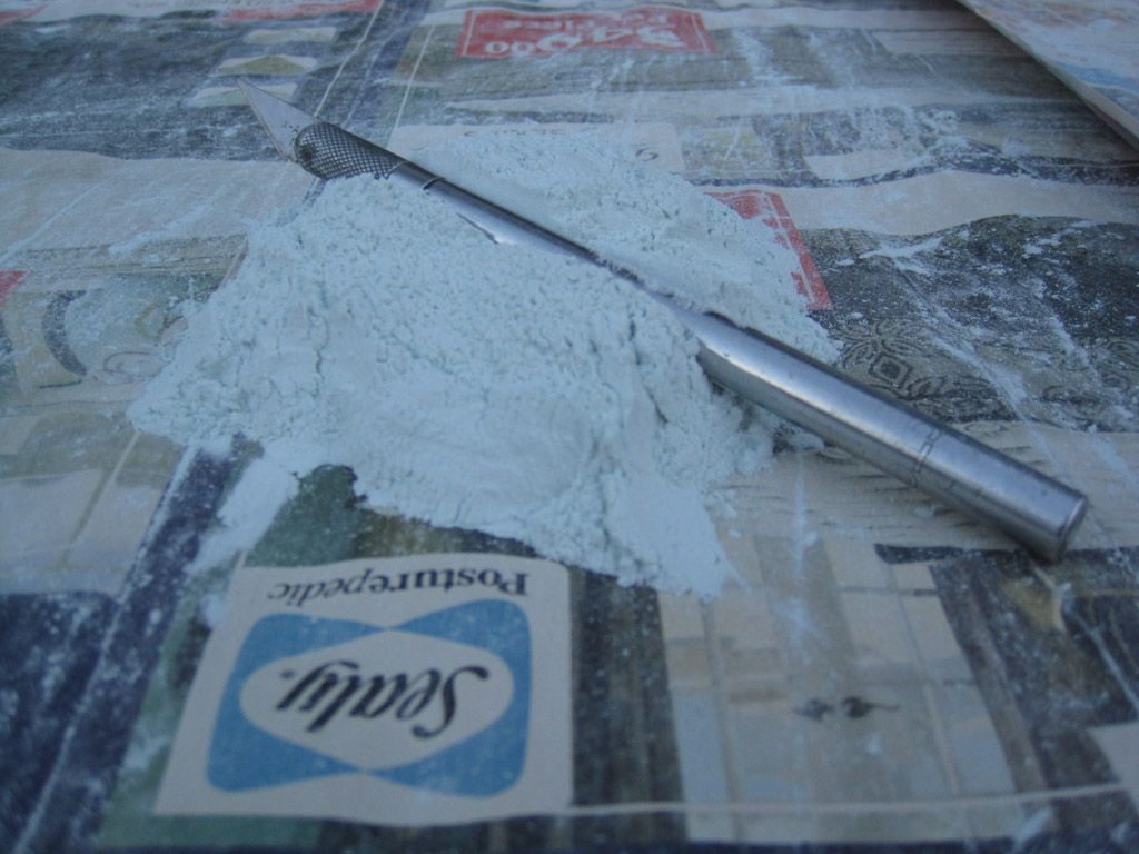 Right, so taking things back to the start for a minute... The printed templates were (lightly) spray mounted on the styrene sheet. Then I used an Xacto chisel to trim each individual component out: 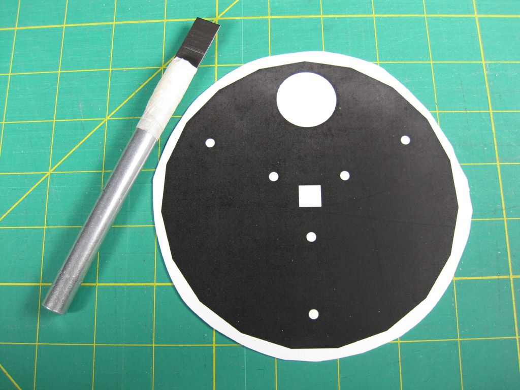 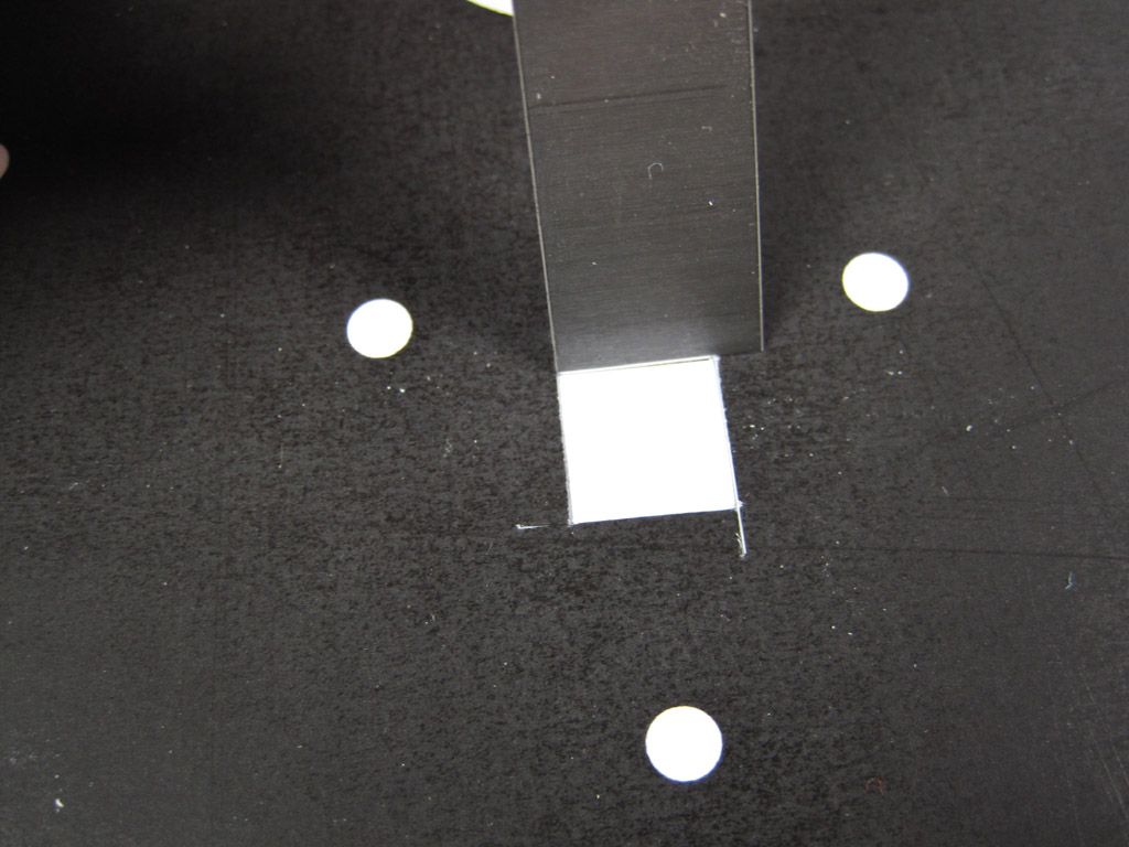 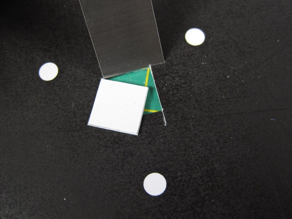 I revised my skin drawing, adding locating lines to show where each rib should be located and merging the whole thing into one continuous piece (rather than individual strips). After trimming out the entire skin, I removed the paper over the ribs (down to bare plastic) and scribed the fold-lines along the length. 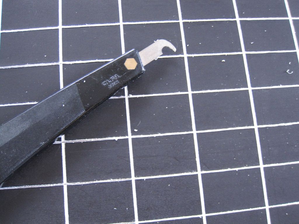 Next, I spray-mounted a strip along the spine. Again, I had marked out locations for each rib section, so once the glue dried, I sliced along the lines, peeled off the paper leaving bare plastic at each rib location. It was then a simple matter of sliding each rib along the spine until it clicked in place in the appropriate slot. Surprisingly effective, pleasingly secure. 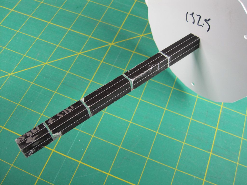 The next step was to align the ribs and attach the braces, keeping everything square and true. To do THIS, I made a simple alignment tool from a set square and some styrene tubing. 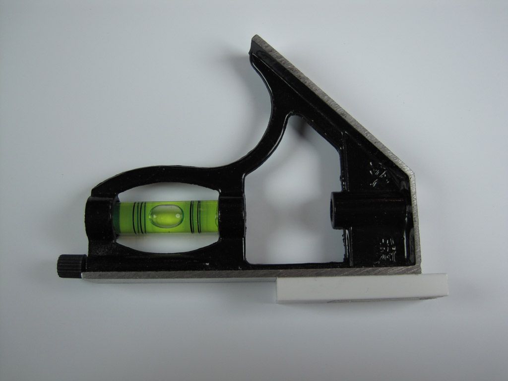 The tubing and square sit on the spine, and the rib gets aligned vertically up against the square. 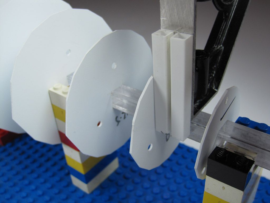 Also visible here is a simple jig made from LEGO. I combined a bunch of plates, then made towers to securely hold the spine perfectly straight and true. This avoided any potential flexing in the acrylic tube spine and, by suspending the whole lot above the work surface, removed all pressure on the ribs. |
|
|
|
Post by Mofo on Jul 24, 2014 13:37:03 GMT -7
After much tedious fiddling (though *FAR* less than the first version), the skeleton was finished: 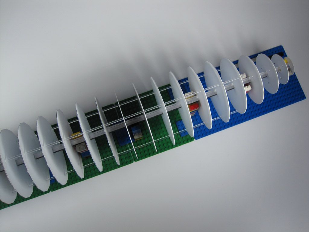 The next step was skinning. I realized the best way to avoid dealing with the whole how-to-remove-spray-adhesive issues was just to avoid it entirely. So I did, by gluing the templated surface INSIDE the model. 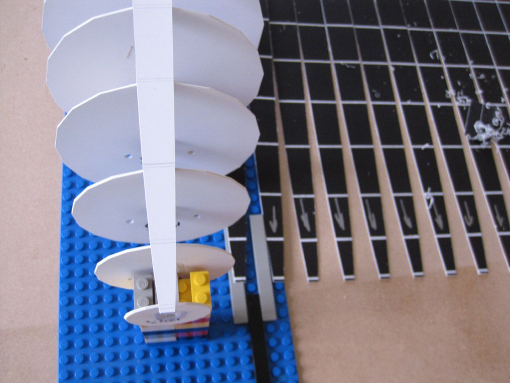 I also realized that trying to glue the skin all in one go would be a can of worms, so I split it into three sections: left, right, and the single bottom panel. The bottom panel was carefully aligned and glued down, as this would be my primary guide for the subsequent assembly. A fraction of a mm off here would be magnified by the time I got to the top. Next, I carefully aligned my first side panel, then wound my way around to the top. It was *still* a handful to glue up, but I was able to carefully wind my way around. As things progressed, a pair of chopsticks became invaluable to keep the rest of the skin from flopping in the way: 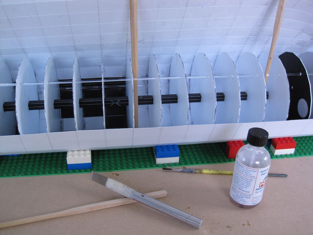 As I got towards the end, I felt a bit like a vivisectionist, or a biology textbook illustration with the skin peeled back on some animal. Also visible here is a handy byproduct of my light spray-adhesiving: a lot of the template popped off easily; since I'd trimmed along the glue lines, I had light score marks in the surface showing where to glue anyway, rendering the actual template largely useless. With the skin attached to the centre section, I glued down the nose and tail sections, trimming to fit as needed. This left me with a nicely covered centre section, but some ugly seams to fill and sand in the nose and tail. Unfortunately, because the styrene had a pleasing droop in between each rib, filling those specific sections, while maintaining a consistent surface, would have been almost impossible. Plus, the scoring and folding along the centre body had left the crease lines quite weak, splitting in some areas. So I made the tough decision to fill and sand the whole thing. All six square feet of it. Which brings us back to this: 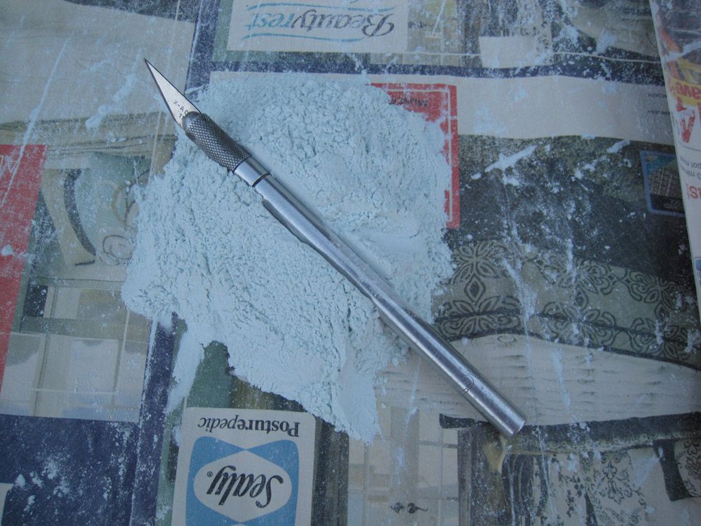 Because of the surface area, using a standard hobby putty would be cost-prohibitive. In the end, I went with an automotive body-filler to level things out and fill in the major gaps. This was... kind of miserable. In the end, I went down to 80grit paper to make the sanding process at least somewhat tolerable. The dust above isn't even a full sanding session on the full Zepp - it was after I'd already started the process. It also had an unexpected side-effect: because the styrene is slightly flexible, and the body putty is fairly hard, the styrene skin would depress slightly as it was being sanded... resulting in a very slight, rounded effect on each skin section. Which, on reflection, is probably more realistic than sunken panels (think about a hot air balloon, for instance). Still, it was a horrendous task (worse than having to re-do the whole balloon!), and sanding dust got *everywhere*. 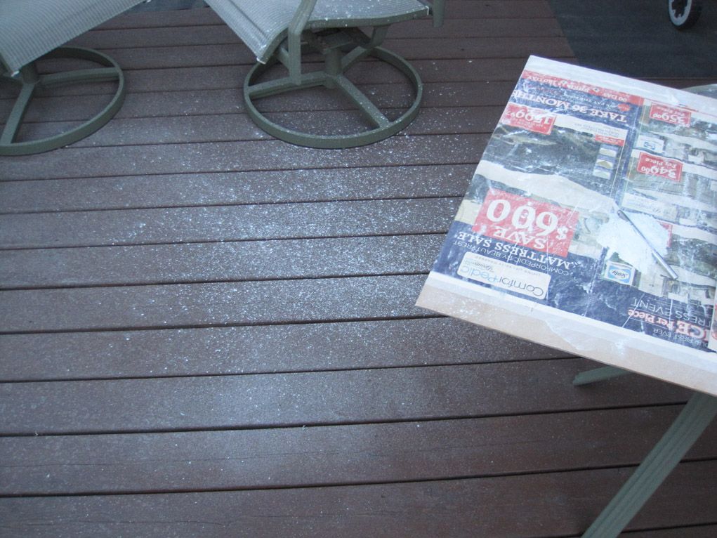 After roughing out the surface with body putty, I filled the voids with an automotive glazing putty. Really nice stuff, by the way, though it felt like I was spatula-ing on tomato paste, due to the colour and texture of the putty. Two coats of filling/sanding with this, and I'm now onto my final spot-filling. It's *much* easier to sand, but I still spent nearly three hours last night with a bucket of water and a sanding block. Also: I sanded through my thumb. Not intentionally, of course, but the slight rubbing from holding the sandpaper against the block has worn through the skin in a few spots. Wheeee! No pics of the filler-coated balloon. It's just a big shape with blue goop on it, then a big shape with red goop on it, and it's now a big shape with patches of red and blue goop on it.  I'll shoot some pics after the (hopefully final) sanding session tonight. Then, it'll be a few coats of a high-build primer to fill the pinholes and final imperfections and even out the surface for paint. Then I can start on the tailplanes, gondolas, engines and such. There's no *way* this will be done by september.  |
|
|
|
Post by Mofo on Jul 25, 2014 14:34:32 GMT -7
Here's the (mostly) finished balloon. 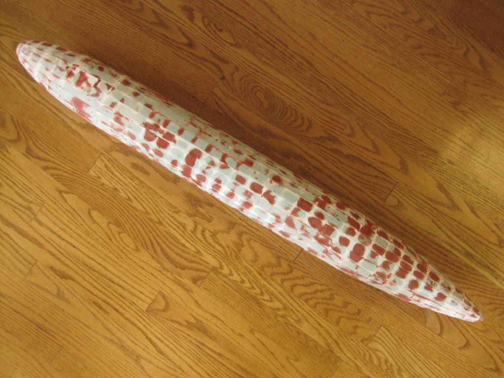 Much, much (much!) filling and sanding. Worst part was breaking through the plastic along many of the seams - should have back filled with CA while I was sealing it up - which necessitated a good deal of corrective surgery to slice open and inject CA. In that sense, I'd have been better off with a poorer fit between the skin sections. But... it's done now. Next up is a heavy coat (or three) of high-build primer to seal in any little pin holes and level out the surface. Plus, my first pass at painting the behemoth. Not sure how I'm going to tackle it. 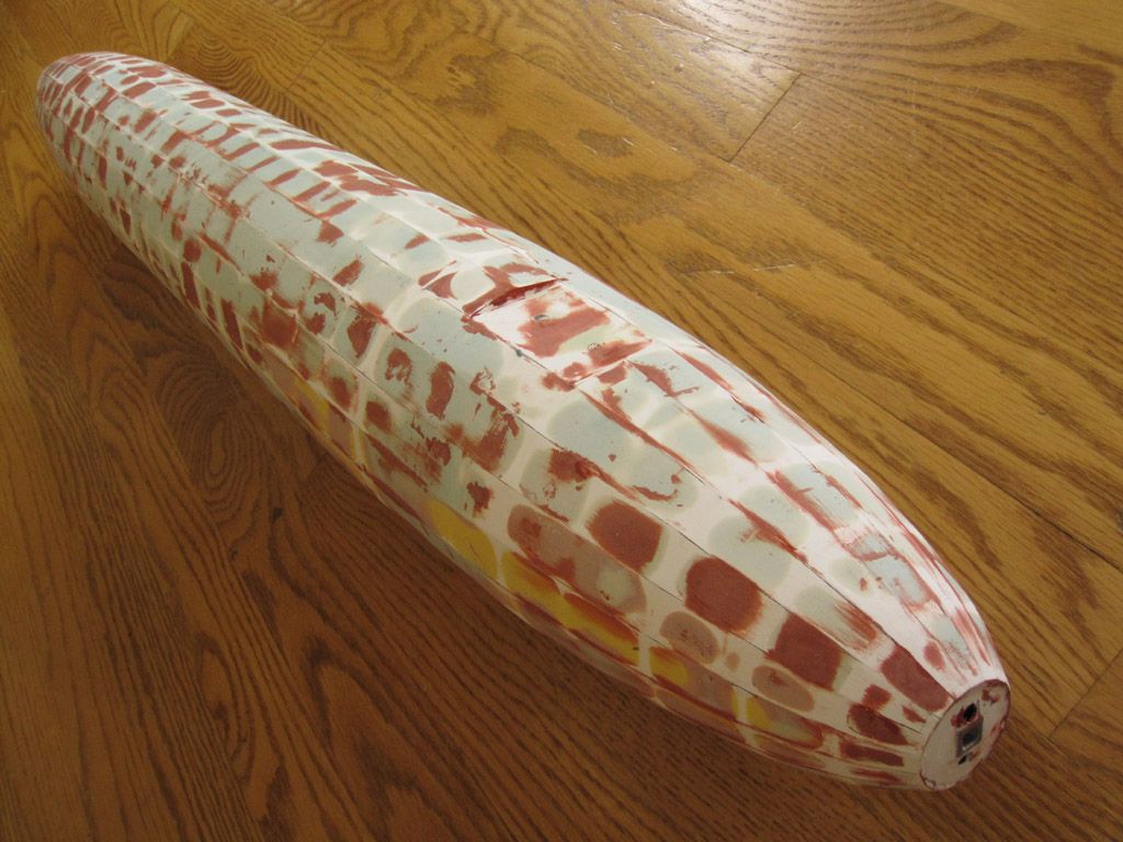 This view gives a good idea of the layers of filler. The yellow stuff is Tamiya's Polyester putty, which was my first go 'round. Great stuff, but too spendy to use in this application, really. The pink areas were next, a slightly flexible, slightly rubbery automotive polyester putty. Not really happy with it - the flexibility made it tough to sand, and it didn't stick as well as I'd have liked. Grey was a normal auto body filler, with not enough hardener; I tried to extend the working time, but it didn't work as well as I'd have liked. Blue is the same filler, with a proper mix. It was tedious doing a slew of small applications, but worked better than minimizing the catalyst. The putty worked fine, though it was harder than I'd have liked when cured. Last is the red-brown glazing putty. Nice stuff, sands easily, I used about 1/2lb of the stuff. 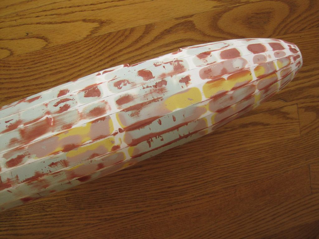 For what it's worth, the full plastic structure (spine, ribs and skin) was - I think - about 1lb 3oz (or 1lb 13oz - can't quite recall). Total weight with putty: 2lb 1oz. |
|
|
|
Post by timmay on Jul 29, 2014 6:47:56 GMT -7
I am truly impressed. Especially with your will to stay the course. Now when you get to the decals, Revell will more than likely pop one in 1/144. Yours in a box of plastic dust, Timmay!
|
|
|
|
Post by Dave Fleming on Jul 30, 2014 6:51:31 GMT -7
Excellent!
|
|
|
|
Post by Dave Fleming on Jul 30, 2014 6:53:41 GMT -7
re painting - copuld you use a full size auto spray gun?
|
|
|
|
Post by Mofo on Jul 30, 2014 8:06:29 GMT -7
Possibly. I'm leaning towards spray bombs, though. Assuming I can find a decent paint match.
|
|
|
|
Post by timmay on Jul 31, 2014 7:30:56 GMT -7
How about Tamiya Silver? You could decant it and if needs be mix with their other Spray Bomb lacquers in order to get the shade you need for that doped look. Timmay!
|
|
|
|
Post by Mofo on Jul 31, 2014 9:48:35 GMT -7
My main reason for wanting to spray-bomb it is because using an airbrush would be hell. Look at your kitchen table. Now imagine trying to airbrush it. That's similar to what I'm up against. I *know* that I'd get probably half way around the nose cone, decide 'fuck this, it's taking too long' and rush through the rest of it. Once I get the main paint blocked in, I can detail paint with an airbrush. And speaking of... They seem to have been CDL, not silver dope. At least, this *class* of Zeppelin. They also used UN-doped linen, or a more open weave (or strips thereof) around the upper half, in the middle of the envelope. This was to help vent excess gas. So it actually *should* be kind of see-through on top. I'll probably go with masking, smoke tint and pastels in the vein of this build (trust me, I DID think about building it from clear sheet for a few minutes): theolivant.pbworks.com/f/Zep3.jpgOne P-Class (same basic airframe, but one cell shorter than mine) was given an experimental camo, but again, just paint over CDL. theolivant.pbworks.com/f/Zep4.jpgi646.photobucket.com/albums/uu186/gatosub/001-12.jpgThen later in the war, the larger Super-Zeppelins were painted black underneath, with a lozenge of normal dope on top. I've seen this depicted both as silver and CDL: theolivant.pbworks.com/f/Zep2.jpgAnd also, worth posting, here's a collection of Zepps (god, this must be HUGE!), which shows how tiny an early P/Q class was (camo, bottom) compared to the Hindenberg (silver, top) theolivant.pbworks.com/f/Zep2.jpgSo I'll probably look for a sandy shade from Tamiya. Maybe one of the ivory or racing white shades. Barring that, I have a feeling there should be something workable in the Citadel range, and if all else fails, there's always Krylon. |
|
|
|
Post by gnat on Aug 12, 2014 12:20:05 GMT -7
Very Very Very........big! and is going to be very very very......big! forever. I built the hawk kit and I still have not painted it. I airbrushed my Gato out in the garage (its every bit as big) it took 4 bottles of Tamiya semigloss black XF-18. I used a detail paint spray brush a cut up from our pencil types. If you have a friend who paints motorcycles he probably has on. Grex makes one its around $299.00 I saw it last week at the Nats
I like what you've done by the way
Gnat
|
|
|
|
Post by Mofo on Sept 26, 2014 15:07:32 GMT -7
Quick update: I've started priming. Needs a little more putty here and there, but I'm pretty pleased. Pics... eventually.  |
|
|
|
Post by timmay on Sept 28, 2014 7:47:21 GMT -7
Whoopee! Timmay!
|
|
|
|
Post by Mofo on Sept 30, 2014 14:25:33 GMT -7
Right: how to make a fin in five steps. First, what you'll need. I've printed out my fin templates (see the first post for a view of the templates). I've already trimmed out the fin's cross section; rather than trying to cut out all the individual ribs in-situ, I'm just replacing them with some styrene square rod: 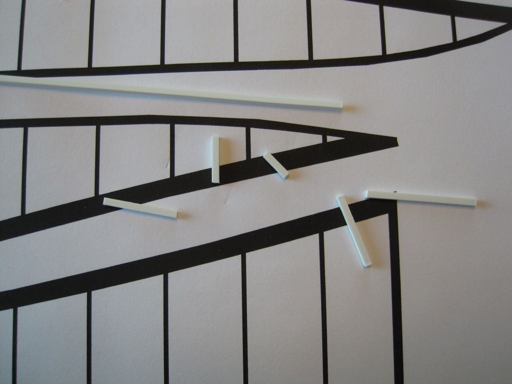 Step 1. Loosely trim your lengths of styrene rod, and tack them down to the template. PVA, contact cement, spray adhesive, CA... even a dab of liquid glue will work, as the plastic adheres slightly to the paper's surface. This sets your alignment and spacing. 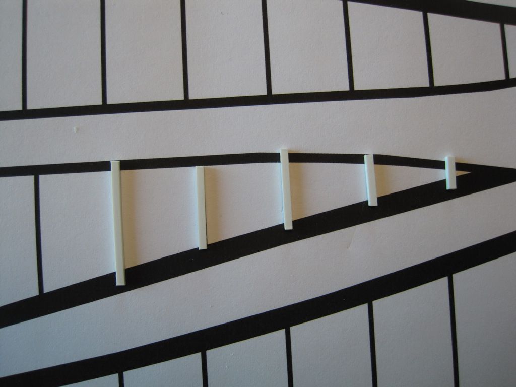 Step 2. Lay your styrene outline, or cross-section, on top of the rods. Use a sharp, single edged razor blade to trim the rods so they fit inside the cross-section; with careful trimming, it should be a nice, snug fit. Add a dab of liquid glue to the end of each rod to join it to the cross section. This gives you your finished fin cross-section, complete with spars: 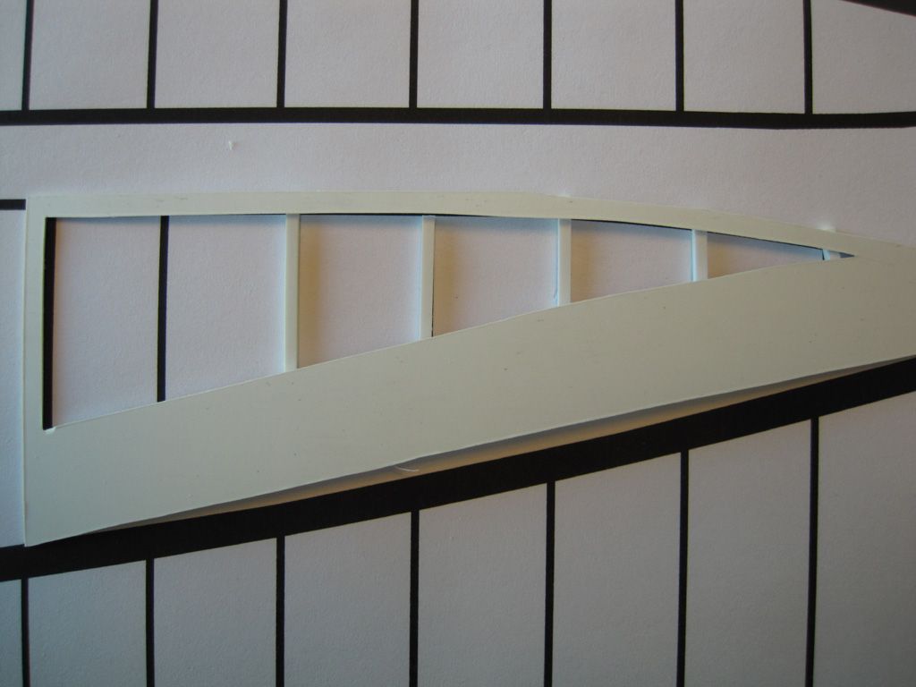 Step 3. Trim out the skin panels for each fin (2x each). Glue to the fin's skin to the skeleton, then place the assembly under a heavy book until the glue cures - you don't want any warpage! If you use liquid glue, as the solvent works on your styrene sheet, you'll get a nice, realistic sag around the framing. 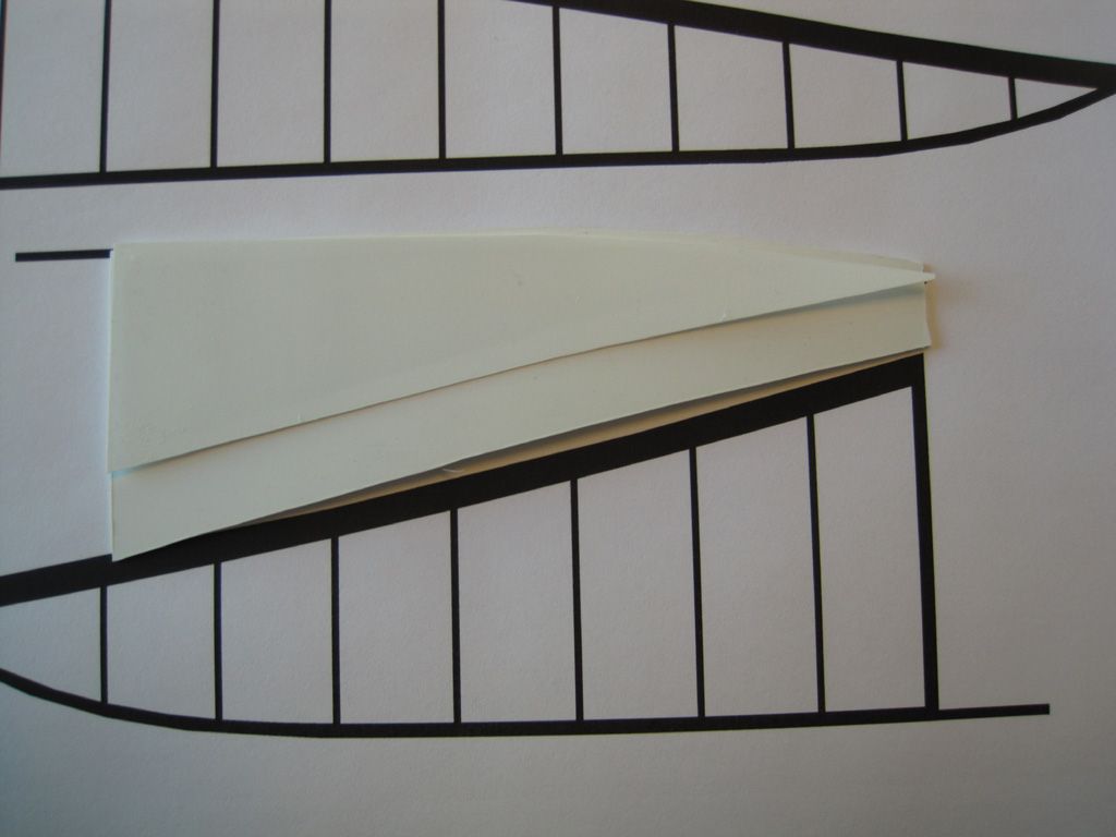 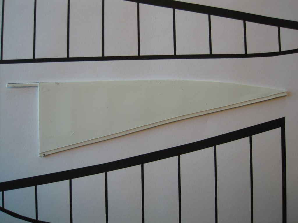 Step 4. Pop the glued assembly off your template. The skeleton is a delicate assembly, but once the skin is on, it's nice and secure. You'll probably have to give the exposed framing a light sanding to remove any stray bits of paper or glue: 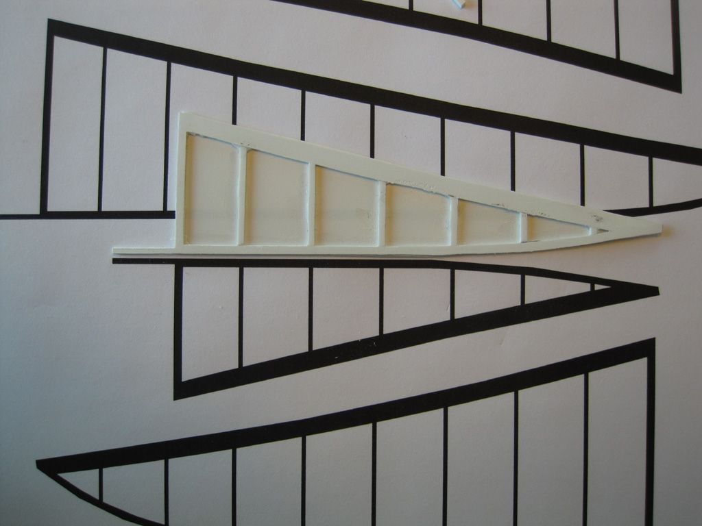 Step 5. Glue the remaining skin section to the exposed framing, again placing the assembly under a heavy book while the glue dries. This will ensure a nice, flat assembly. Once the glue is cured, you can fill any imperfections and round off the edges. Also, while you CAN drill or notch holes for some locating pins BEFORE the fin is all sealed up, the finished assembly is actually translucent if you hold it up to a light, so it's just as easy to mark these off later. 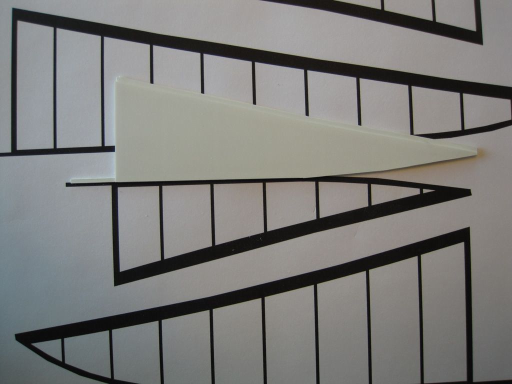 |
|
|
|
Post by timmay on Oct 5, 2014 6:17:21 GMT -7
Marvelous, simply marvelous! Timmay!
|
|
|
|
Post by Mofo on Oct 5, 2014 21:55:14 GMT -7
Second can of primer is on. Well, 2/3 of a can, anyway. But first... the gun platform. For self defense, Zeppelins were armed with a number of machine guns; each gondola had a pair of gun stations, and there was an open-air platform on the top of the nose, accessible via a ladder from the front gondola. I get the willies looking at the pictures of Zeppelins launching, imagining being on that lonely platform 50+ feet up in the air. I can't even imagine standing on top of that massive, floating balloon at several thousand feet. If you thought WWII turret gunners had it rough, at least they weren't standing outside. And had parachutes... Incidentally, the gun platform just happens to be almost the exact same size as the Sopwith Pup I'll be building along side the Zepp, so again, if you're wondering about how big this thing is, scroll up to the tiny airplane in front of the Humbrol tin, then keep that in mind when you look at the gun platform. Anyway, my pics of the actual build weren't great, so here are some renders showing the process. Step 1: Mark off and cut out the required skin sections. Luckily this falls between along two bulkheads, so it's easy to find the cut lines. 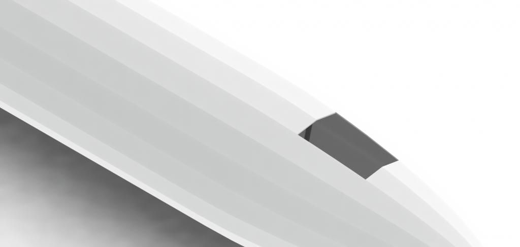 Step 2: Inlay a section of styrene sheet to fill the hole. 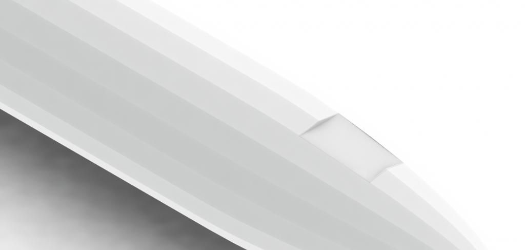 Step 3: Realize that you've mixed up the measurements for the platform size (d'oh!), so you have to replace part of the skin. Not a hard task: I just printed out the relevant section from my templates, chamfered the edges then glued/filled/sanded in place. Always frustrating to have to fix your own stupid mistakes, though. 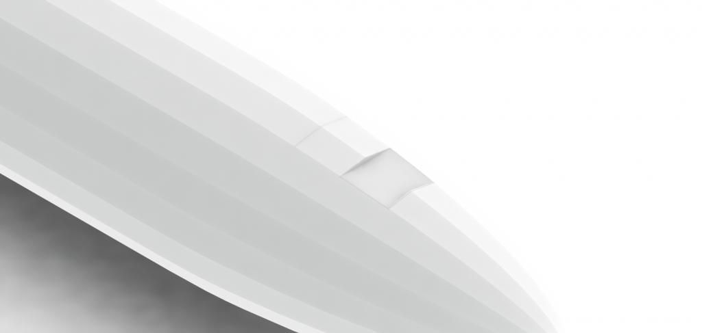 Step 4: Cut the platform itself out of styrene sheet, using templates copied from the paper model. This gave me the overall dimensions of the gun platform, as well as the cross-section pieces which let me align it easily: aligning a flat piece of plastic card is fiddly; aligning the vertical edges is much simpler. Just cut out the overall shape, scribe along the fold lines and the styrene folds cleanly. 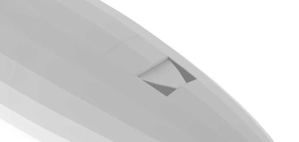 Step 5: Fill the gaps at the front with styrene sheet. Again, the edges were chamfered then the filler pieces glued down and trimmed to size. 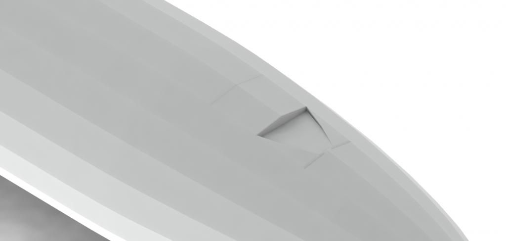 All pretty straightforward. The only real difficulty came with the flexibility of the styrene, but a healthy squirt of CA underneath makes it more rigid, and less prone to flexing when you sand. With the gun platform in place, the whole thing got primered (again). Which is where it's at now. Things are looking decent; it definitely needs a wet sanding, but the surface is relatively level. There are a few spots that need refining though - pinholes, scratches, cracks and glue/putty lines. Nothing really major (I mean, compared to body-puttying the whole thing!), BUT! The surface is so large, it's hard to remember where all the surface imperfections are - and easy to miss a few - so I've gone over the entire balloon and used a pencil to circle all the areas that need further attention. Makes it look a tad spotty at the moment, but it should pay off in the end. 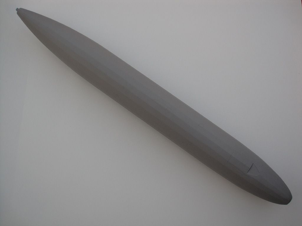 Nose area, showing the areas to be fixed, as well as a view of the gun platform. You can also get a feel for the 'pillowing' effect on the skin. 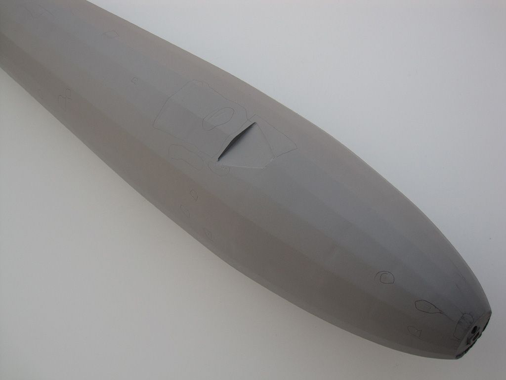 Closer view of the nose, with a better view of the faults and platform. It's not super-critical to get a flawless fit around the front of the platform, as this will actually be getting a small wind shield made from sheet stock, which will cover the area. Still, there are a few issues to be addressed. 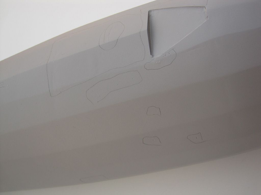 ...and a view of the tail, showing more glitches, and probably a better view of the pillowing (though it seems more prominent here than IRL). This also gives a view of the skeleton: some 5/8 acrylic square tube used to keep all those rib sections aligned properly and rigidly. Once my nose and tail caps get printed, they'll slot right on to this spine piece. Theoretically. I hope... 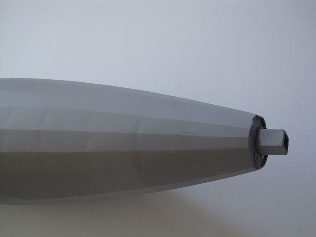 |
|
|
|
Post by Mofo on Oct 6, 2014 17:44:57 GMT -7
Tailplanes test fitted. Need to tweak the fit to blend them in, but it's a start. It's *finally* starting to look like an airship, rather than a big cigar. 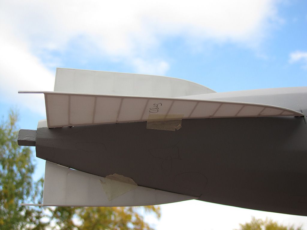 Note the see-through effect on the tailplanes. Hopefully I can maintain this through paint. Hopefully... 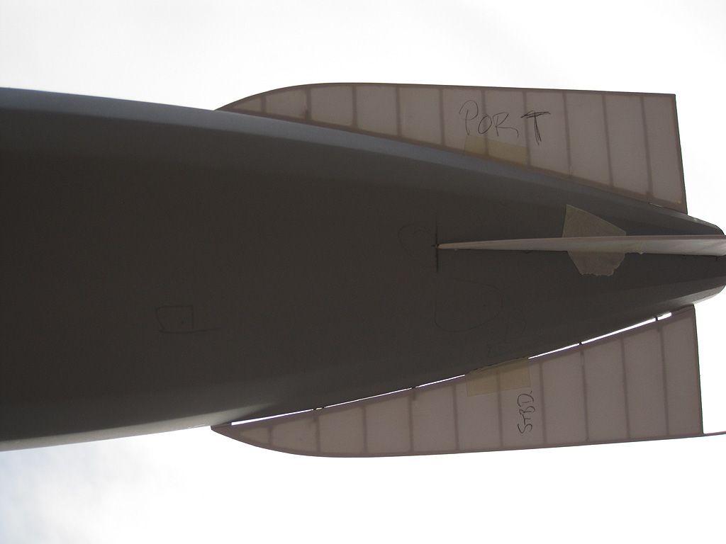 |
|
|
|
Post by Mofo on Oct 7, 2014 14:41:59 GMT -7
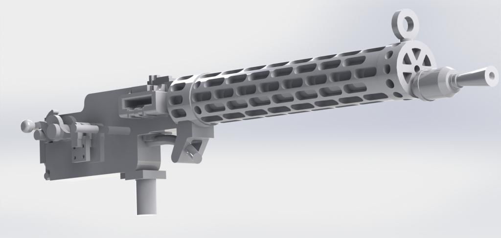 Finished the CAD work on the Spandaus. Well, I say finished; I expect these will be too fine to actually print, but I'd rather start with too much detail rather than too little. The really clunky looking ring sight, for instance, is only .1mm thick (.004") 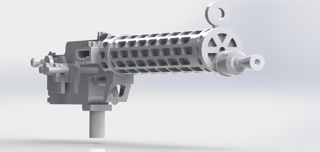 But wait... what's that in the barrel, the sharp-eyed readers among you will say. 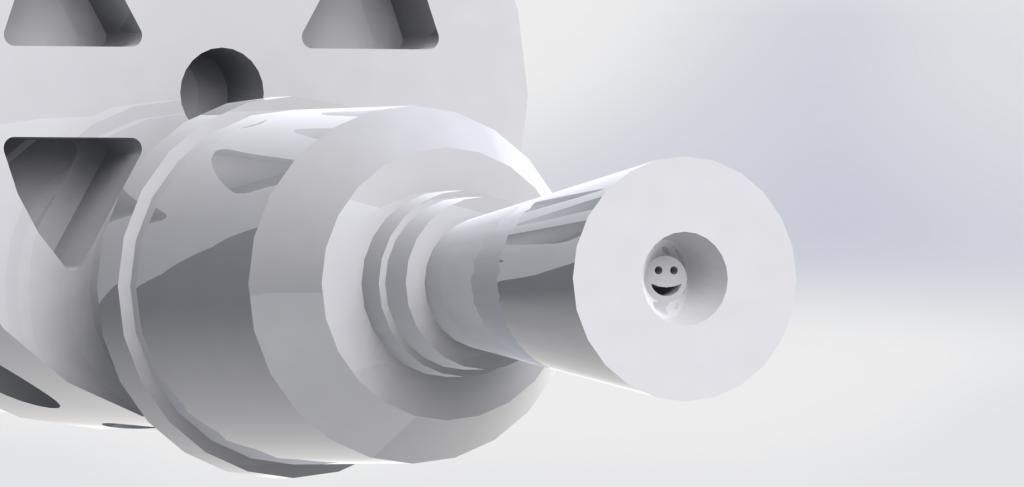 This is a good illustration of the problem with CAD. You can zoom in... almost infinitely. Which makes your detail look thick and clunky. It's really easy to lose sight of how big a part will actually be, and how all that detail you've lovingly created will be unprintable, or invisible to the naked eye. Each of those eyes is a mere .008mm (.0003"!) in diameter. But hey, they're smiley-faced Spandaus, how could I *not*?  The really, really NICE thing about CAD is that, after you've spent hours making one model, it takes mere seconds and a few clicks of a mouse to make more. Enough for the Zeppelin, plus a few extras for good measure: 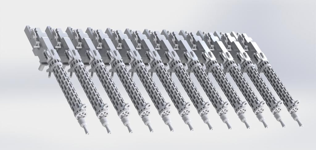 I believe that, when you're referring to this many of the gun, the correct term is 'a ballet'.  ...and now to add it to the stack of bits to be printed. Next up: engines! |
|
|
|
Post by Dave F on Oct 15, 2014 14:12:47 GMT -7
Mike, maybe a silly question, but what scale is it? I'd been assuming 1/72 but....
|
|
|
|
Post by Mofo on Oct 16, 2014 14:21:36 GMT -7
1/144. It's almost exactly 4' long, and about 6" in diameter. The larger scale would have been awesome and now that most of the dirty work is behind me I find myself thinking "maybe I should have...", but I also realize the filling and sanding probably would have killed me. Plus, what the hell do you do with an 8' long tube? It would be kind of impossible to display.
At 1/144, it's still big and impressive, yet small enough to fit over a fireplace or on top of a bookshelf or something.
|
|
|
|
Post by gnat on Nov 11, 2014 7:26:00 GMT -7
Mike all I can say is WOW! What a redo ought to call it Phoenix it truly arose form the ashes of the first one. I have the Hawk Graf Zeppelin ready for paint. Thonk I'm going to rattle can it then adjust with the airbrush.
gnat
|
|
|
|
Post by Mofo on Dec 10, 2014 0:39:58 GMT -7
I believe the phrase is "photodump".  Got my prints back from RapidFab. They use the same kind of printers as Shapeways' Frosted Ultra Detail, but it's a much smaller operation, running higher resolution, and it's cheaper to boot. I think the prints look MUCH better. Full gallery is here, for anyone who is interested. s21.photobucket.com/user/IronChefMoFo/library/parts/3d/prints2 I'll try to pick out a few highlights. A couple of notes up front. You *CAN* see visible print layering, and striations from the print head. It's not the worst I've ever seen, but it will need cleanup (filler primer + sanding). Also, because the acrylic resin is translucent, it's a pain to photograph. It also means you're seeing surface issues on BOTH sides of the part. Remember that when you're looking at the surfaces. It's also interesting to note, that because of the rough surface finish, the parts stick to a microfiber cloth like velcro. Again, nothing that a light sanding won't improve, but they're *not* ready to go straight from the box. 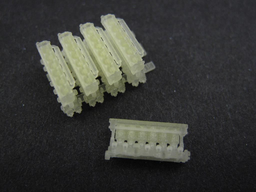 Engines. Not much to say. They seem to be mercifully smooth, requiring little clean-up, but it's a little tough to say for certain until they're primed. You'll notice that they have a slight discolouration at their cores; that's from the support wax (more later). 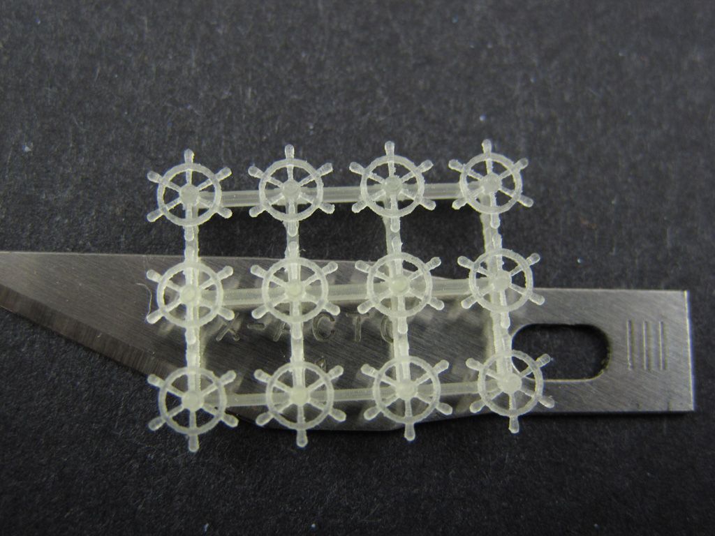 Ships wheels. Again, they seem pretty clean, which is lucky since they'll be almost impossible to clean. If I recall correctly, the connecting points on the spokes are around .3mm. Also, it's a good illustration of one thing 3D printing could be really, really good at: replacing PE. Instead of having flat, two-dimensional brass parts, print 3D shapes. They don't use much material, they're thin, so they'd have fast print times, and they're more realistic. Interesting thought for the future. 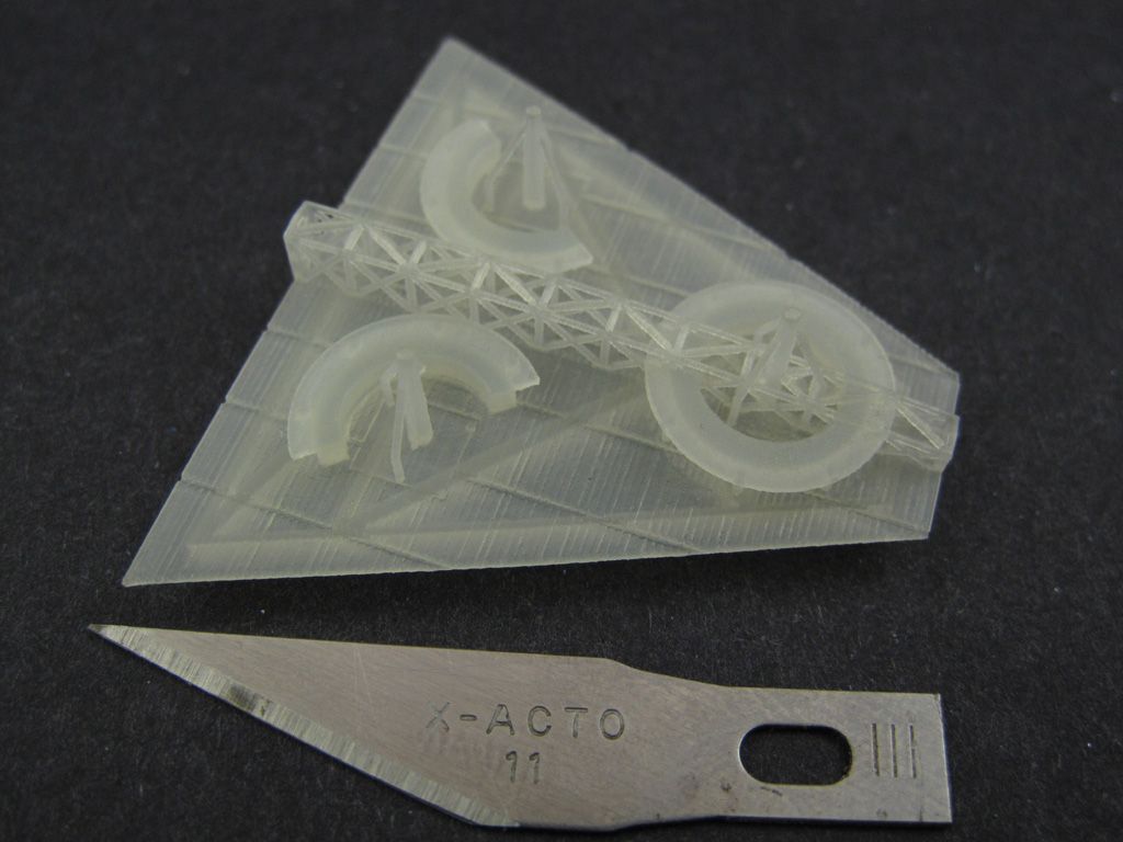 Gun platform. There's pretty much zero chance I could have scratchbuilt this without resorting to PE. Now I just need to inset it into the fuselage top. It almost feels like cheating.  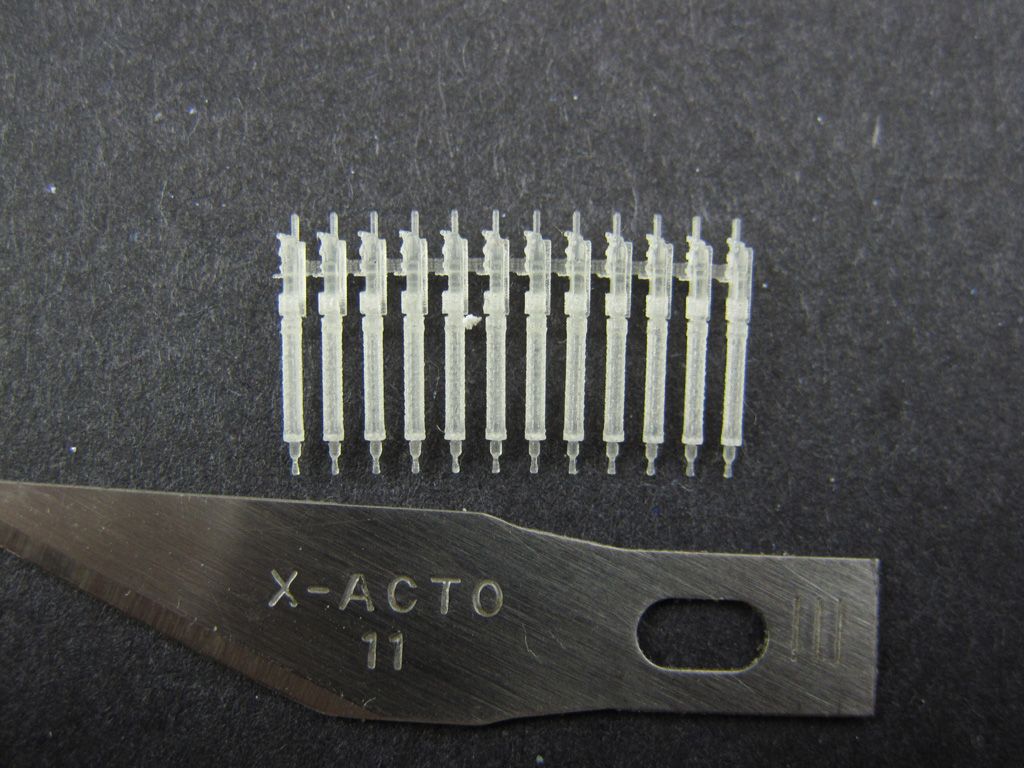 ...and the guns. I'll need to primer these before I can tell how they turned out. I *can* make out the gas vents, but anything other than that is just too small. I mean, they're certainly good enough, I'm just not sure how good at the moment. (this is one of the downsides to the translucency) 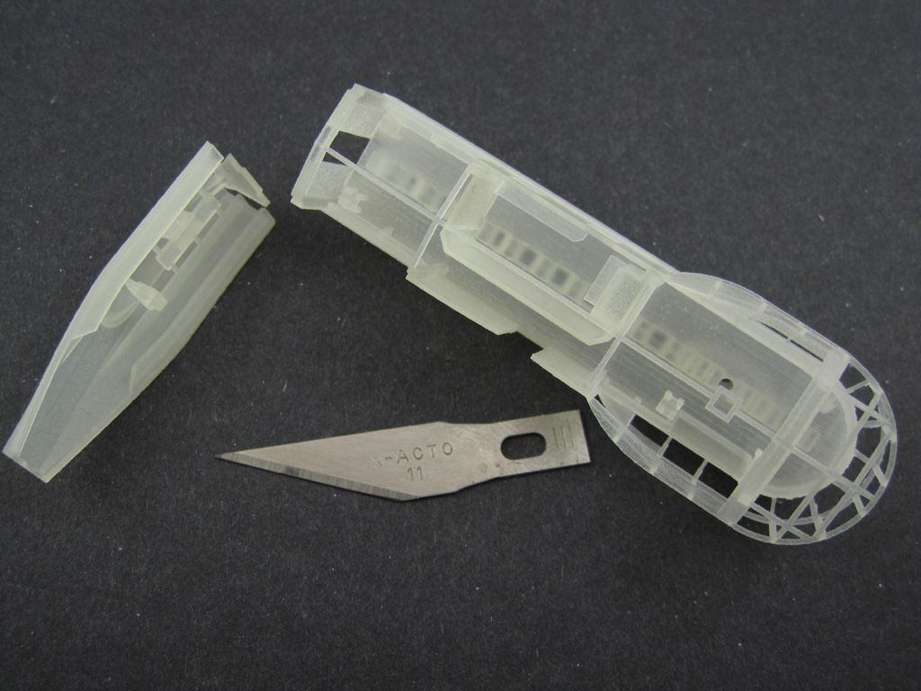 Front gondola pieces. The front control gondola was actually split in half, with the command section separated from the engine section, apparently to avoid the vibrations transferring through. I decided to mimic this, and split the engine bay off. 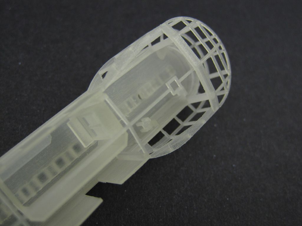 Interior details. Note the square stools - I think they're about 1mm square. The framing will all have to get glazed over... somehow. I could make up a vacform master, or just cut panels from acetate. Leaning towards the latter. 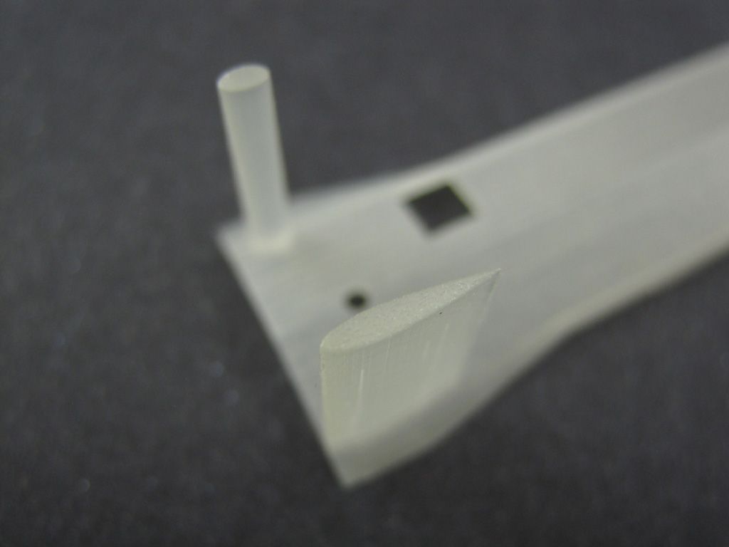 Command section roof, showing the knife edge to the fairing, and some of the print lines, basically just to get a feel for the print texture. 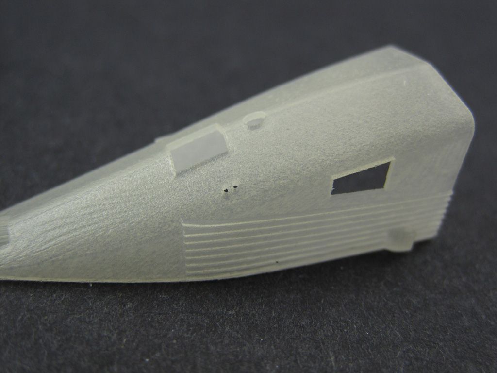 And the engine section's roof, again to show the texture of the print. You can see print layering on the left side, and a slightly rough surface on top. The raised lines along the side are meant to be there. Oh, and note the scoop towards the bottom/front; it's been printed open.  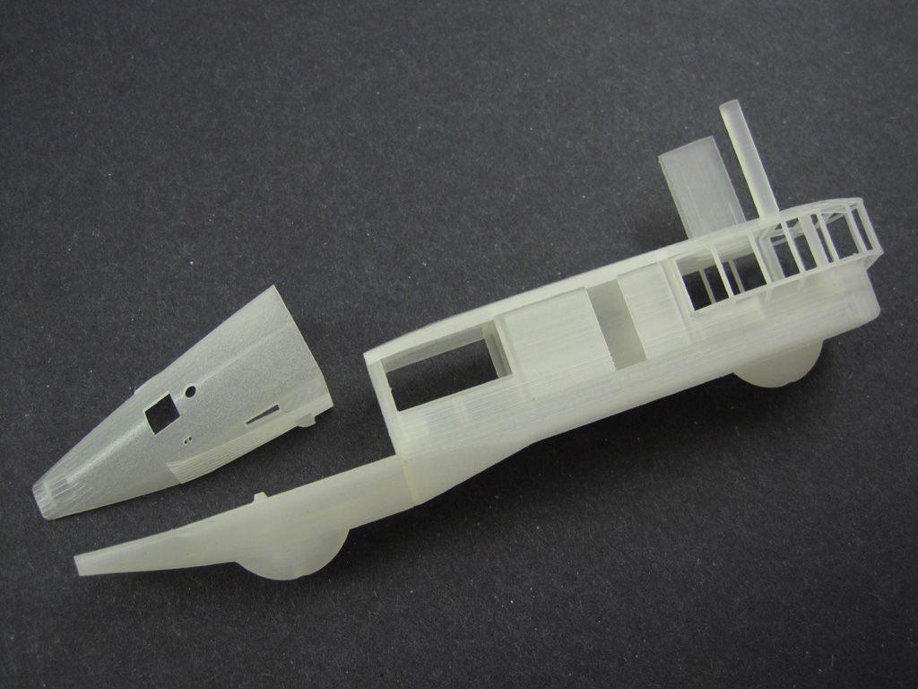 The various parts all just press-fit together. A couple of dots of CA are all that will be needed. 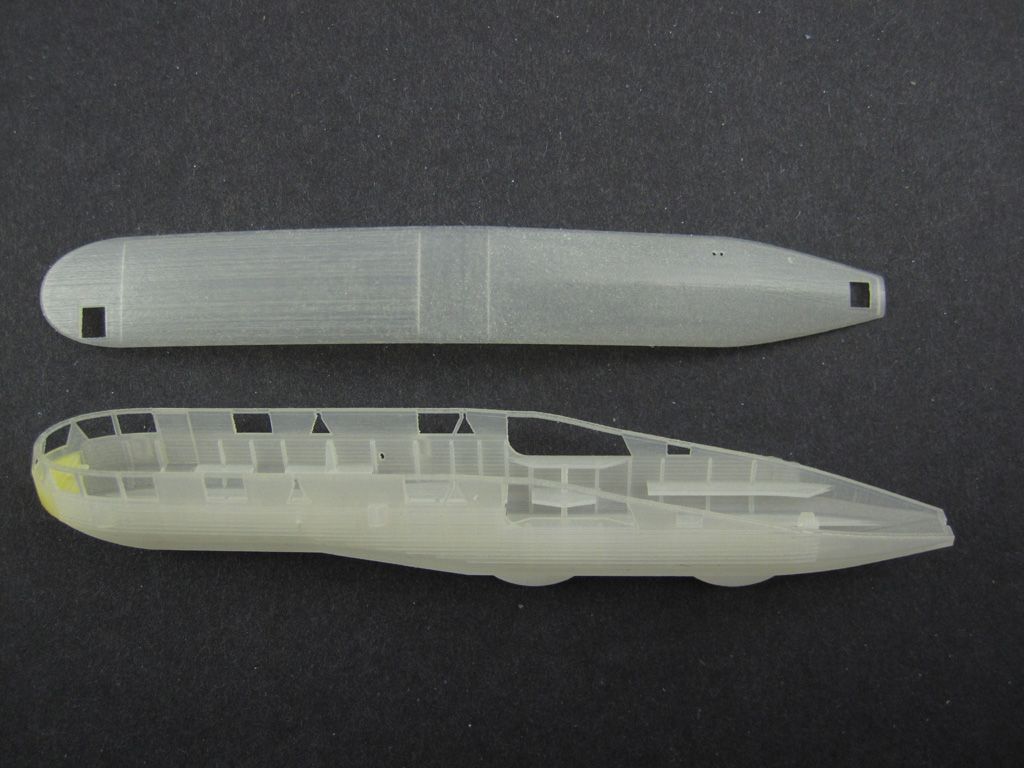 Rear gondola and roof. This one had three engines, so would have been loud! Again, notice the yellowish tint at the nose... 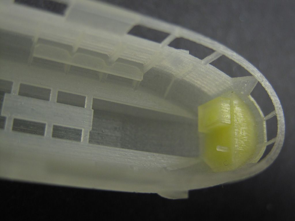 I forgot to include an escape hole in the model, so the yellow substance is the support wax. The 3D print head prints out the resin, but it also prints wax to support the model. That's why you can print layers that would otherwise be floating free in space; in the physical print, they're not, they're printed on top of wax, which gets melted away in post processing leaving your free-floating part. At least, it does as long as there's a way for the wax to flow out. I'll probably drill a few small holes and heat the model up to empty the wax out, just in case it causes problems in the future. 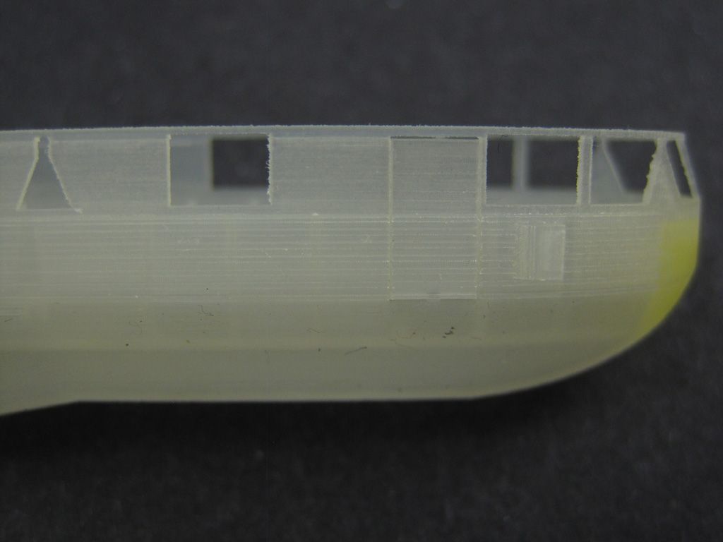 Speaking of free-floating, notice the door. I gave it a .1mm gap around the edges, leaving small tabs attaching it at the top and bottom. A couple of quick swipes of a pico saw and it's free. 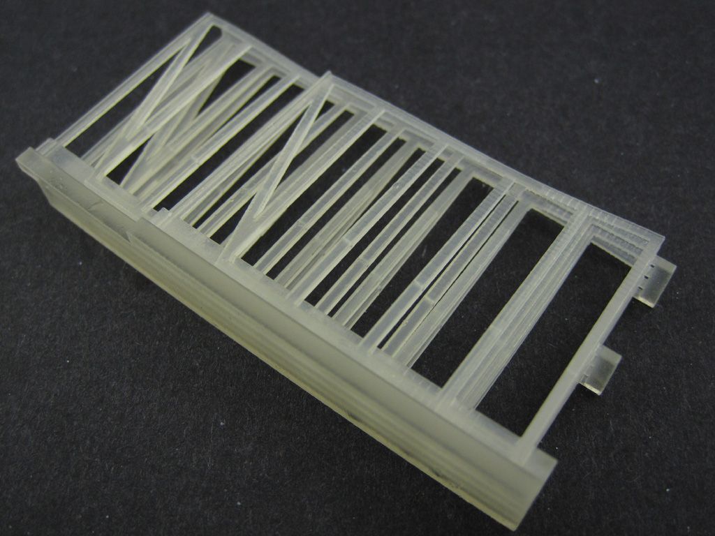 Rudders. These warped slightly, but they're *very* thin at the edges. I used a few blocks and spacers to hold the parts together through shipping. Also, note the faint line through the fins, running roughly across their middles... 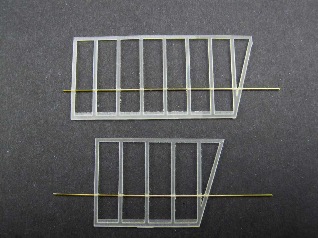 Those are printed-in holes for the rudder hinge rods. They just needed to be lightly reamed out with a .5mm drill bit, then slid onto some brass rod. That should add some strength to a relatively delicate structure. The rudder cores themselves will get skinned in thin sheet styrene, then the brass rod fill slot into holes in the body and tailplanes; I opted to print them largely because it was easier to obtain the proper airfoil cross section that way, rather than through careful, tedious sanding. 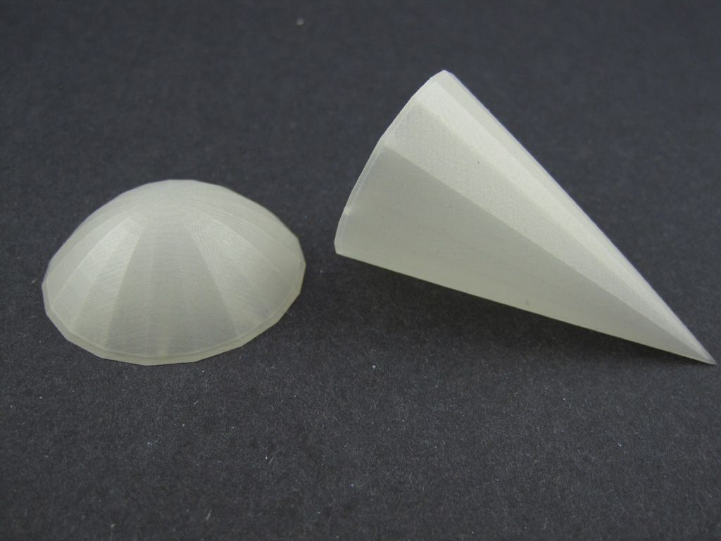 And finally, the nose and tail caps. These are way more precise than I could have managed, carefully filing and sanding styrene sheet. And they're sized to simply slide over my acrylic rod spine. It's the first time I've had a fully, complete envelope. I'll be using putty to fair them in and refine my facets. The down side is, I won't be able to 'rotisserie' my balloon for painting any more. Unless I make them removable... 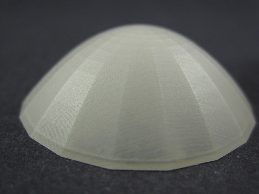 Finally, another shot showing texture on the nose cap. You can clearly see the (nice, crisp) facets running sort of like longitude around the dome. If you look closely along the 'latitude', you can also see facets introduced when the model was converted from CAD to a 3D printable file format. This converts shapes into polygons (triangles), so, for instance, a nice, smooth sphere becomes a lumpy geodesic dome. In this case, the smooth arc of the dome became a just-barely visible series of flat facets. Kinda neat. Now I just need to give everything a thorough cleaning to remove all traces of wax and mineral oil, then shoot a coat of primer to see what I've *really* got. |
|
|
|
Post by gnat on Dec 10, 2014 8:14:00 GMT -7
This gets more and more interesting...model on
Gnat
|
|
|
|
Post by kyrre on Dec 29, 2014 8:12:50 GMT -7
I am impressed. I am.
|
|
Dave F, must remmber my login!
Guest
|
Post by Dave F, must remmber my login! on Dec 29, 2014 10:06:49 GMT -7
Wow, that really shows what 3D printing can do
|
|
|
|
Post by Mofo on Dec 30, 2014 22:25:38 GMT -7
Yeah. It's interesting that they're using essentially the same printers as Shapeways, who are the people that did my first 3D printed bits, which were pretty disappointing. Partly it's to do with my increasing experience - better part orientations, more thought into resolution, etc. But a big part is just that this company is running for quality rather than quantity. Impressive stuff.
|
|


 I'll shoot some pics after the (hopefully final) sanding session tonight. Then, it'll be a few coats of a high-build primer to fill the pinholes and final imperfections and even out the surface for paint. Then I can start on the tailplanes, gondolas, engines and such.


