Post by Mofo on May 14, 2015 13:18:35 GMT -7
One of the most awesome-looking cars ever to turn a wheel: Profil 24's Golden Arrow LSR car. www.profil24-models.com/model-kits-modeles-reduits/en/gamme-au-1-24e/171-golden-arrow-lion-napier.html

I fell in love when I saw this build video a couple of years ago: www.youtube.com/watch?v=H2HuxKWrUkg Got a screaming deal on the kit last winter, and have been playing with it off and on ever since. I'm basically aping this build, with a few tweaks of my own: www.britmodeller.com/forums/index.php?/topic/234946505-golden-arrow/
The kit itself is... okay. Quite simple, just a dozen major parts including a massive, one piece, 13", 1/2 lb body. Details are somewhat simplified, leaving room for extra detailing. My kit also suffered from a fair bit of warping and pinholes. These are not MFH-quality castings. A long soak in scalding water helped straighten the curved radiator panels, but even after heating the wheels in a warm oven, I wasn't satisfied with the wheels. In addition to being deformed (out of round), they had some fairly major seam lines. So my first step was to sketch some CAD renders and 3D print some replacements:
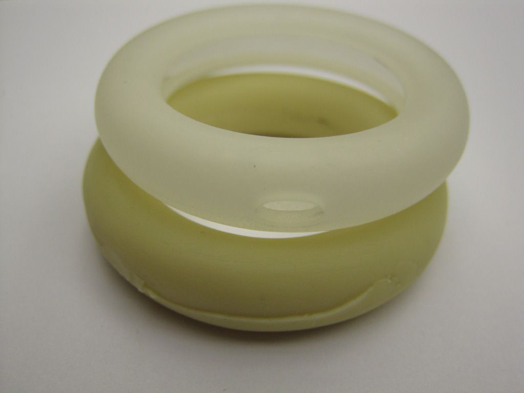
An added bonus is that I was able to add a small flat spot to each wheel, to improve the 'sit'.
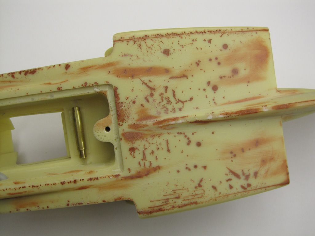
Next came the pinholes. The underside of the car is riddled with them, so a fair amount of drilling, hacking, grinding and filling was needed. I'm still not 100% satisfied, and I may simply skin the entire underside in brass sheet in the end.
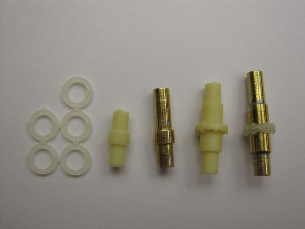
Moving along to the radiator mounts, the Britmodeler build notes that the kit's resin mounts are a little weak, so I scratched some replacements, soldering up some telescoping brass tube, with some 3D printed flanges for detail.
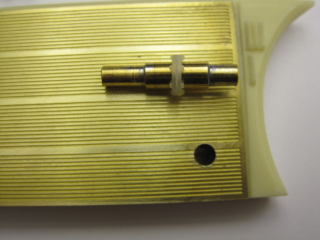
The radiator fins were missing locating holes - just a solid brass rectangle - which made their construction far more tedious than it should have been. The resin sidepods had the locating holes drilled out, then the PE radiators were attached to the inner faces. Once the glue had dried, I then drilled back through the locating holes to punch through the PE, before finally gluing on the outer radiator faces.
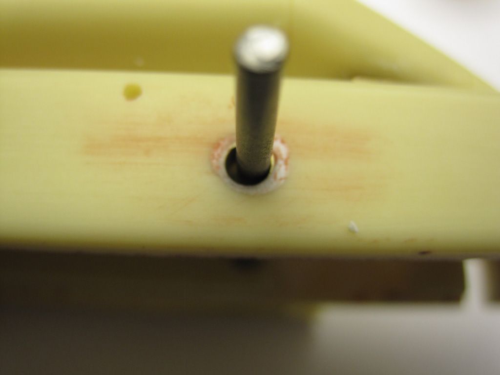
To finish off the assembly, I drilled through the body, embedding a length of brass tubing to give a nice, tight fit all around. A length of steel wire adds even more rigidity. End result: the radiators are a nice snug, secure fit and will not sag.

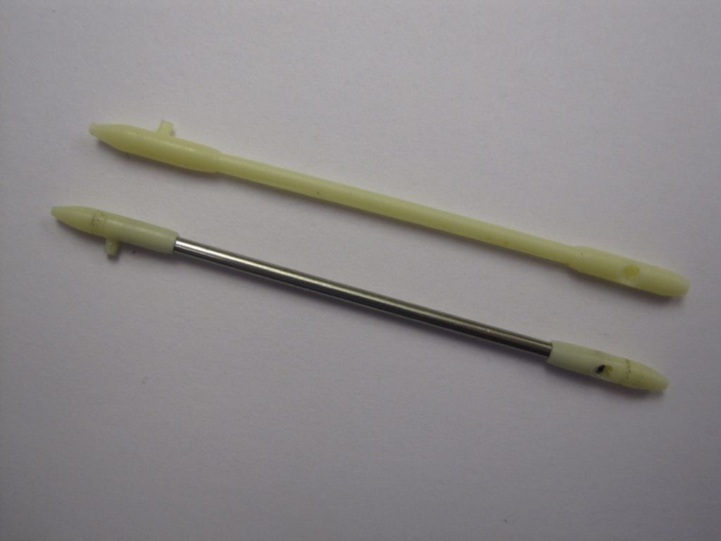
Staying in that same area for a moment, rather than tediously cleaning the kit's resin pushrods, I replaced their centre sections with a length of hypo tubing. The resin end caps were rounded (and pointed) on a lathe, then drilled out to accept the hypo rods. Ironically, the yellow resin end caps will be painted chrome, while the stainless rod will be painted gold. Oh well...
Moving to the inside, the kit just has a simple hole on the sidewall for the shifter. Not acceptable. It wouldn't be hard to scratch a replacement, but since I was having some stuff 3D printed anyway, this allowed for a more precise part. The sidewalls were thinned down, then a notch cut into the side, some aluminium tubing 'drive shafts' added, along with the shifter housing.
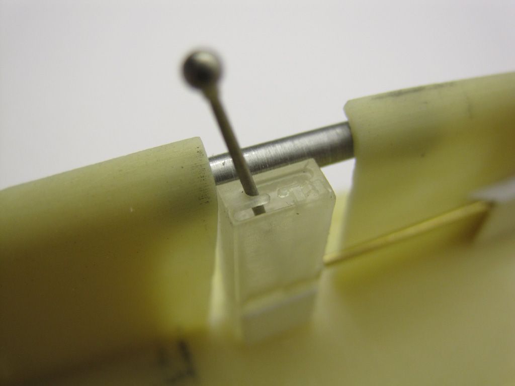
The gear lever itself is Hobby Design; one of their Ferrari 250 gear levers. Looks much nicer than the kit's resin lump. I also replaced the steering column with a replacement made from machined aluminium tube:
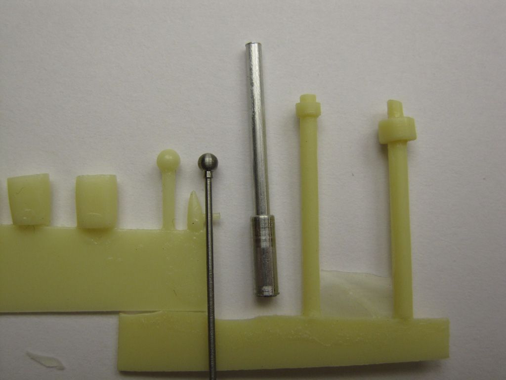
Just a shame that it will end up being painted black.
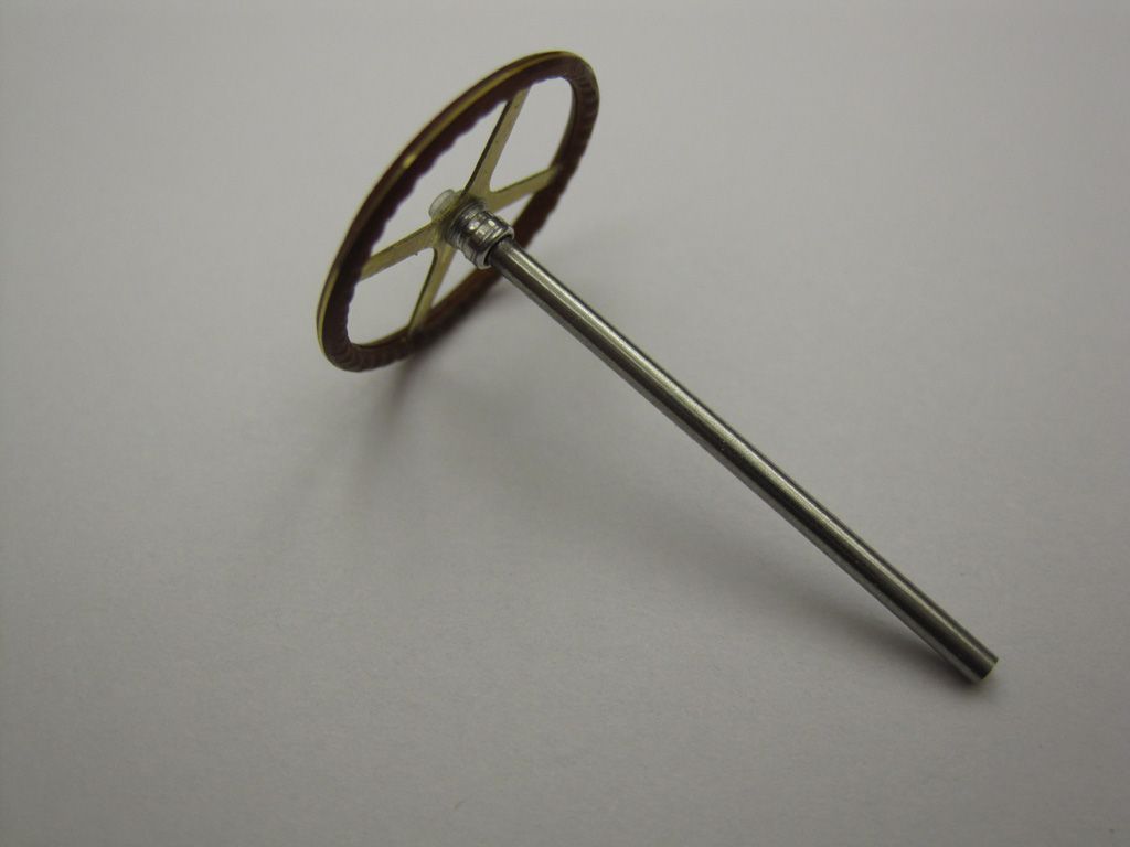
The steering wheel also got a 3D printed hub piece (it's so much easier adding perfectly spaced and sized nuts in CAD than trying to do it by hand

Moving to the right side, again the sidewalls were ground down from behind so I can fit the (other) drive shaft and a cutout made for the handbrake.
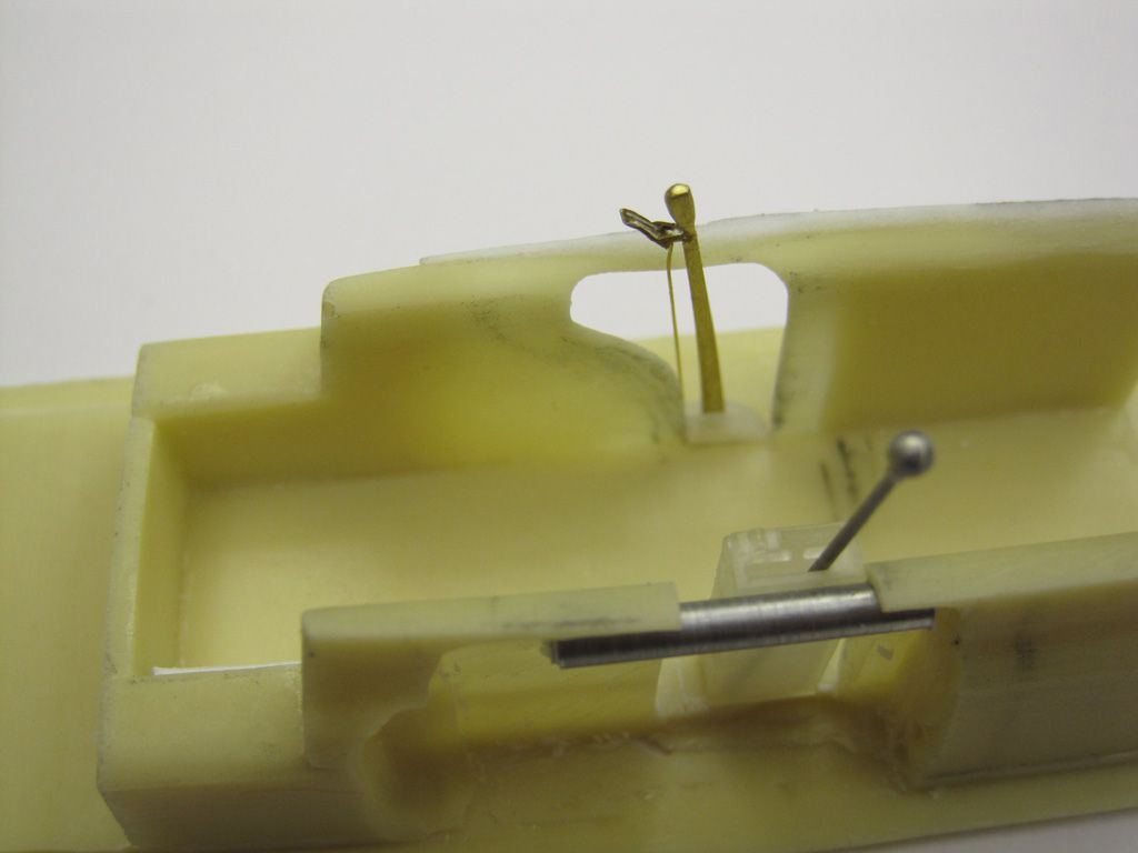
The handbrake itself was made by filing some brass rod to shape. A scrap bit of PE (a 1/72 Eduard F-16 bomb shackle!) made a perfect 'trigger', and some .2mm brass wire serves as the cable. These slot neatly into a machined ABS disc hinge. Quite pleased with the result:
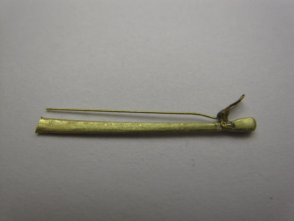
Moving back outside, it was time to tackle the 'telescope'. The car was so long that in order to keep it straight, the mounted a sight down the middle. (again, how awesome is that?!?) The kit's resin lump would need a lot of tedious cleanup, so it was easier to simply scratch a replacement out of telescoping aluminium tubing. A short section was chucked in a lathe and turned down to the appropriate diameter - this gave me the three narrower 'rings', and the 'stepped' end piece. The segments were trimmed off, measured out and CAed to a length of narrower tube:

Again, shame it has to be painted. Looks a whole lot better though, doesn't it?
And the other reason I wanted to scratchbuild a replacement: The sight is actually see-through, now!
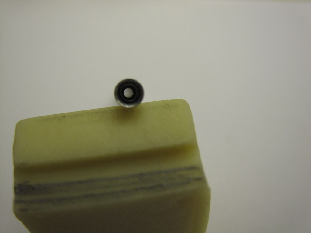
The next item on the list is the carb intakes, which is where I'm currently stalled. The kit lacks any intakes, with simple recessed panel lines noting their locations. Fortunately, the kit's PE fret is the *perfect* size to scratchbuild some replacements.
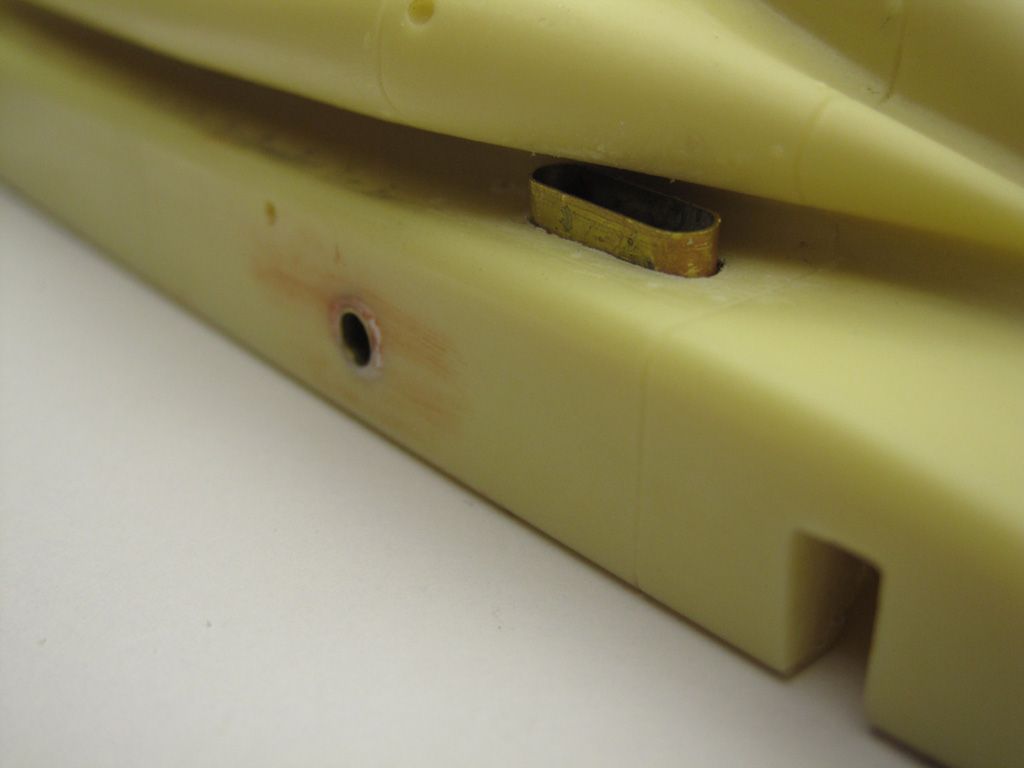
The appropriate areas of the body were ground down and drilled out, then the intakes were built using annealed lengths of the PE frame.
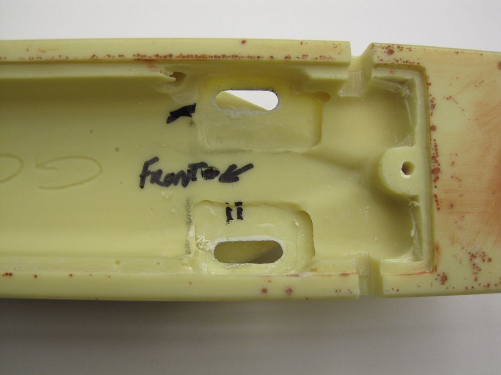
Now I'm stalled while I debate whether or not to add some sort of detail inside the scoops. They *will* be somewhat visible, so I should probably add... something. But I have no idea what an aircraft-engine-cum-LSR-car carb should look like, so I may well go for some oily rags instead. You know... to avoid any debris falling into the carbs. (would they have used tennis balls back in the day?)
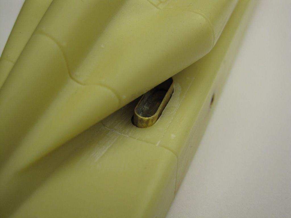
After that, it's brakes and an instrument panel, then I think I'll be ready for some paint!

I fell in love when I saw this build video a couple of years ago: www.youtube.com/watch?v=H2HuxKWrUkg Got a screaming deal on the kit last winter, and have been playing with it off and on ever since. I'm basically aping this build, with a few tweaks of my own: www.britmodeller.com/forums/index.php?/topic/234946505-golden-arrow/
The kit itself is... okay. Quite simple, just a dozen major parts including a massive, one piece, 13", 1/2 lb body. Details are somewhat simplified, leaving room for extra detailing. My kit also suffered from a fair bit of warping and pinholes. These are not MFH-quality castings. A long soak in scalding water helped straighten the curved radiator panels, but even after heating the wheels in a warm oven, I wasn't satisfied with the wheels. In addition to being deformed (out of round), they had some fairly major seam lines. So my first step was to sketch some CAD renders and 3D print some replacements:

An added bonus is that I was able to add a small flat spot to each wheel, to improve the 'sit'.

Next came the pinholes. The underside of the car is riddled with them, so a fair amount of drilling, hacking, grinding and filling was needed. I'm still not 100% satisfied, and I may simply skin the entire underside in brass sheet in the end.

Moving along to the radiator mounts, the Britmodeler build notes that the kit's resin mounts are a little weak, so I scratched some replacements, soldering up some telescoping brass tube, with some 3D printed flanges for detail.

The radiator fins were missing locating holes - just a solid brass rectangle - which made their construction far more tedious than it should have been. The resin sidepods had the locating holes drilled out, then the PE radiators were attached to the inner faces. Once the glue had dried, I then drilled back through the locating holes to punch through the PE, before finally gluing on the outer radiator faces.

To finish off the assembly, I drilled through the body, embedding a length of brass tubing to give a nice, tight fit all around. A length of steel wire adds even more rigidity. End result: the radiators are a nice snug, secure fit and will not sag.

Staying in that same area for a moment, rather than tediously cleaning the kit's resin pushrods, I replaced their centre sections with a length of hypo tubing. The resin end caps were rounded (and pointed) on a lathe, then drilled out to accept the hypo rods. Ironically, the yellow resin end caps will be painted chrome, while the stainless rod will be painted gold. Oh well...

Moving to the inside, the kit just has a simple hole on the sidewall for the shifter. Not acceptable. It wouldn't be hard to scratch a replacement, but since I was having some stuff 3D printed anyway, this allowed for a more precise part. The sidewalls were thinned down, then a notch cut into the side, some aluminium tubing 'drive shafts' added, along with the shifter housing.

The gear lever itself is Hobby Design; one of their Ferrari 250 gear levers. Looks much nicer than the kit's resin lump. I also replaced the steering column with a replacement made from machined aluminium tube:

Just a shame that it will end up being painted black.

The steering wheel also got a 3D printed hub piece (it's so much easier adding perfectly spaced and sized nuts in CAD than trying to do it by hand


Moving to the right side, again the sidewalls were ground down from behind so I can fit the (other) drive shaft and a cutout made for the handbrake.

The handbrake itself was made by filing some brass rod to shape. A scrap bit of PE (a 1/72 Eduard F-16 bomb shackle!) made a perfect 'trigger', and some .2mm brass wire serves as the cable. These slot neatly into a machined ABS disc hinge. Quite pleased with the result:

Moving back outside, it was time to tackle the 'telescope'. The car was so long that in order to keep it straight, the mounted a sight down the middle. (again, how awesome is that?!?) The kit's resin lump would need a lot of tedious cleanup, so it was easier to simply scratch a replacement out of telescoping aluminium tubing. A short section was chucked in a lathe and turned down to the appropriate diameter - this gave me the three narrower 'rings', and the 'stepped' end piece. The segments were trimmed off, measured out and CAed to a length of narrower tube:

Again, shame it has to be painted.
 Looks a whole lot better though, doesn't it?
And the other reason I wanted to scratchbuild a replacement: The sight is actually see-through, now!


The next item on the list is the carb intakes, which is where I'm currently stalled. The kit lacks any intakes, with simple recessed panel lines noting their locations. Fortunately, the kit's PE fret is the *perfect* size to scratchbuild some replacements.

The appropriate areas of the body were ground down and drilled out, then the intakes were built using annealed lengths of the PE frame.

Now I'm stalled while I debate whether or not to add some sort of detail inside the scoops. They *will* be somewhat visible, so I should probably add... something. But I have no idea what an aircraft-engine-cum-LSR-car carb should look like, so I may well go for some oily rags instead. You know... to avoid any debris falling into the carbs.
 (would they have used tennis balls back in the day?)
After that, it's brakes and an instrument panel, then I think I'll be ready for some paint!

